Rotary Cutting Tool Having an Adjustable Cooling Mechanism

Active Publication Date: 2011-09-08
ISCAR LTD
View PDF5 Cites 30 Cited by
  • Summary
  • Abstract
  • Description
  • Claims
  • Application Information

AI Technical Summary

Benefits of technology

[0039](a) varying the position of the relocatable seal along the center pin from a first sealing position to a second sealing

Problems solved by technology

In such a case, the axially rearwardmost rows of cutting inserts are unnecessarily cooled.
As a result, the coolant volumetric flow rate is ineffectively used since it could have been directed in its entirety to the active rows only.
This leads, of course, to unnecessary operation costs which could be saved.
Even t

Method used


Image

  • Rotary Cutting Tool Having an Adjustable Cooling Mechanism
  • Rotary Cutting Tool Having an Adjustable Cooling Mechanism
  • Rotary Cutting Tool Having an Adjustable Cooling Mechanism

Examples


Example

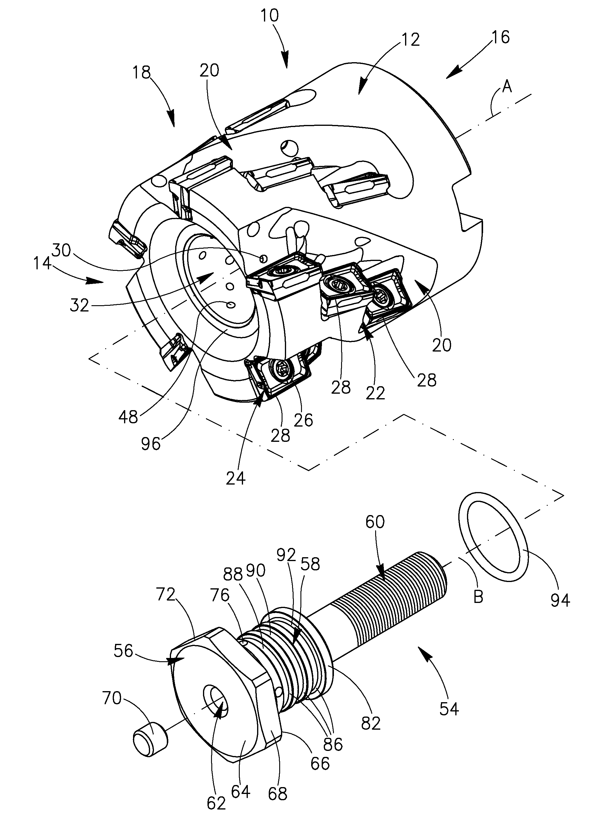
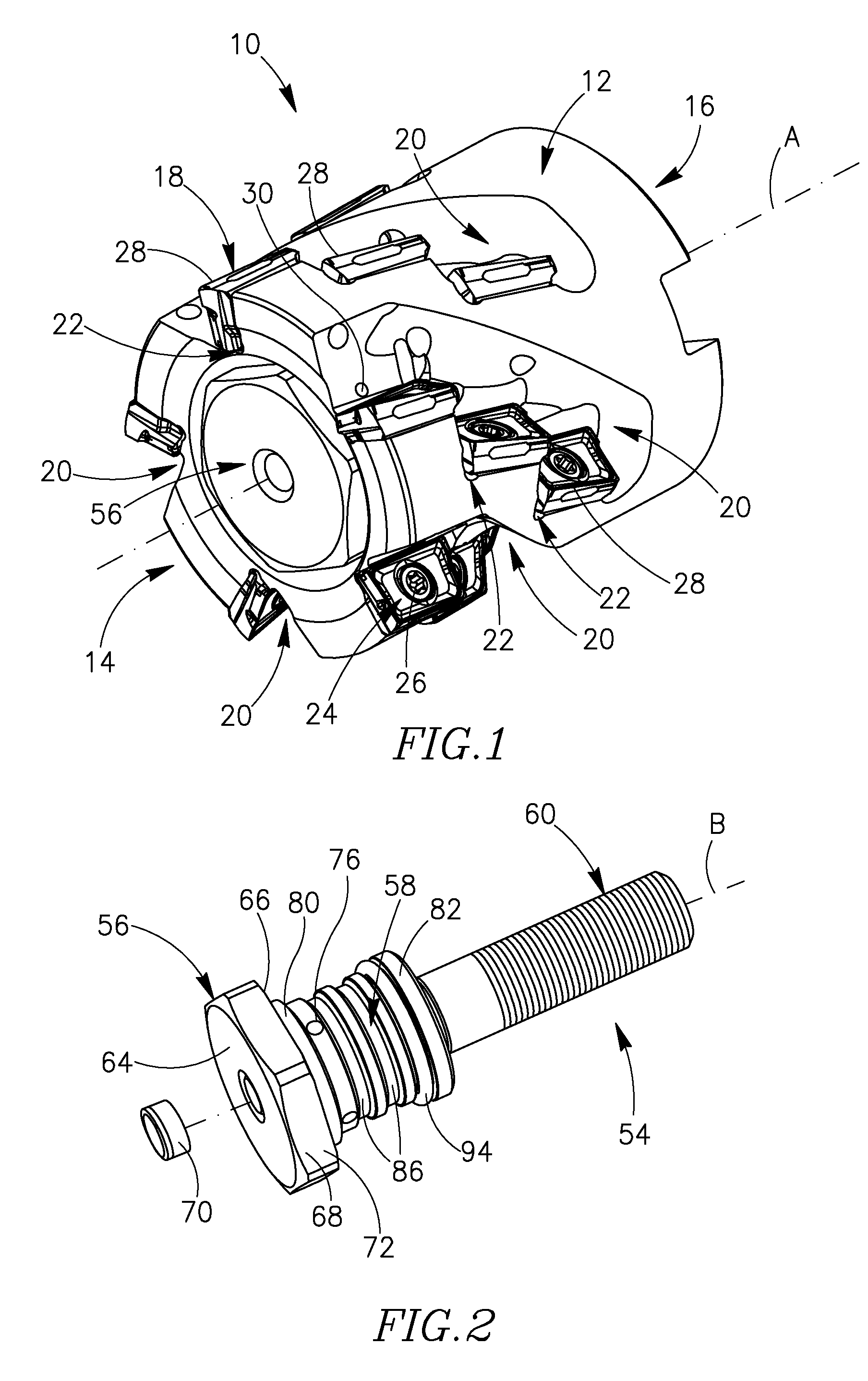
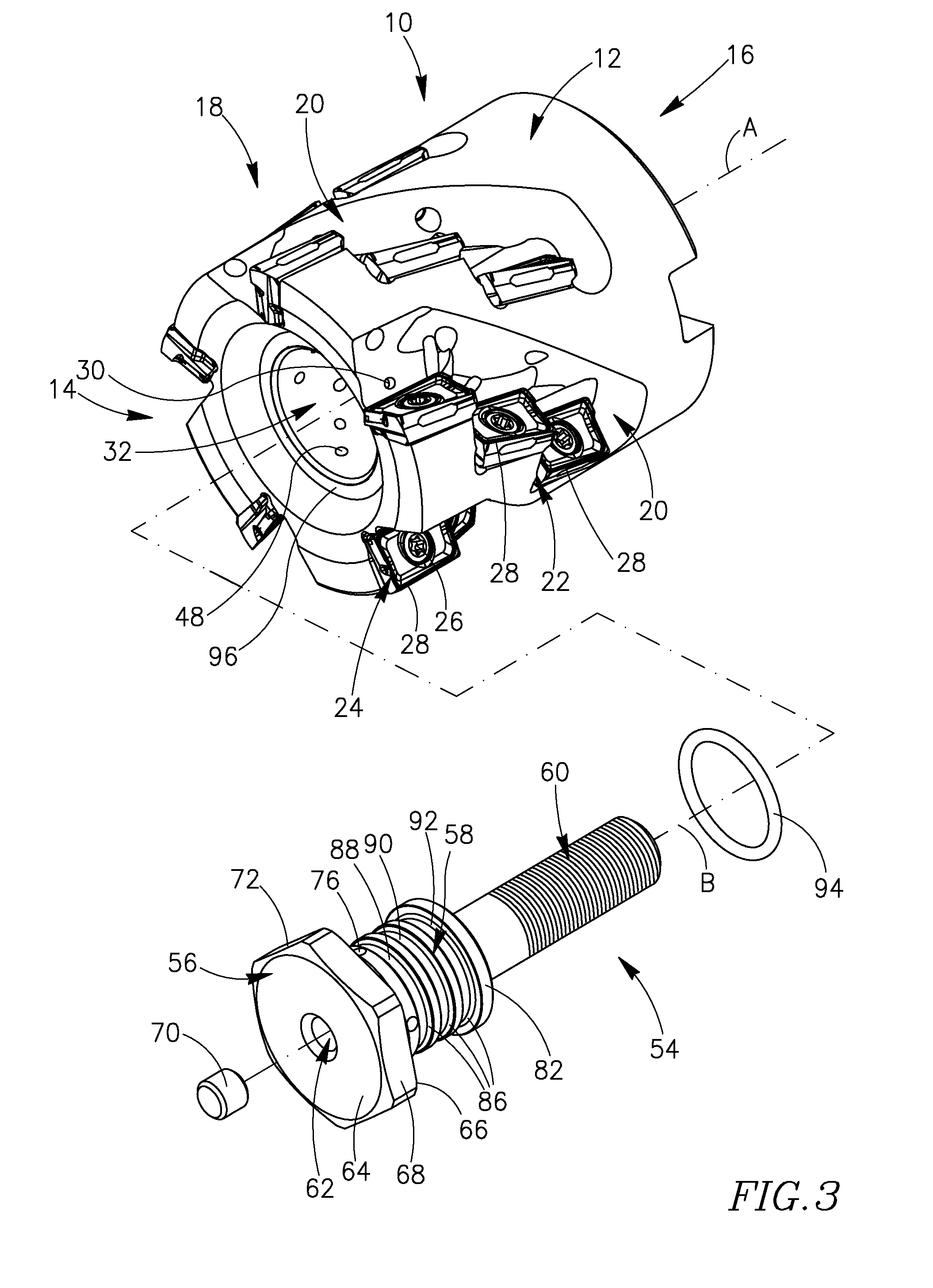
[0053]Attention is drawn to FIGS. 1 to 7, showing a cutting tool 10 in accordance with the present invention. The cutting tool 10 has an axis of rotation A, defining a forward to rearward direction, and comprises a tool body 12 having a body front face 14, generally perpendicular to the axis of rotation A, a body rear face 16, opposite the body front face 14, and a body peripheral face 18 extending from the body front face 14 to the body rear face 16.

[0054]The tool body 12 is provided with a plurality of flutes 20 formed on the body peripheral face 18 and extending rearwardly from the body front face 14. The cutting tool 10 shown in the drawings is provided with five flutes 20. It should be understood, however, that the cutting tool 10 according to the present invention is not limited to having five flutes 20 and any number of flutes 20 may be equally applicable, for example, one, two, three and so on.

[0055]Each flute 20 comprises a plurality of insert pockets 22 that are axially di...


PUM


Abstract

A milling cutter, having an adjustable cooling mechanism, has a tool body having a body central bore. At least one flute is formed on a body peripheral face. Each flute comprises a first row of insert pockets and at least a second row of insert pockets axially rearwardly displaced from the first row. The cooling mechanism includes a center pin having at least two grooves axially spaced apart from one another along the length of the center pin. A relocatable seal is seated in one of the grooves. When the relocatable seal is seated in a first groove, the body central bore is in fluid communication with cooling holes associated with a first number of rows of inserts; when the relocatable seal is seated in a second groove, the body central bore is in fluid communication with cooling holes associated with a second number of rows of inserts.

Description

FIELD OF THE INVENTION[0001]This invention relates to a rotary cutting tool, such as an extended flute milling cutter. More particularly, this invention relates to such cutting tools having internal cooling ducts.BACKGROUND OF THE INVENTION[0002]Extended flute milling cutters are well known in the industry. They enable using one or more sets of cutting inserts, each set comprising several consecutive cutting inserts arranged at the periphery of the cutter, axially overlapping each other, in order to form a long peripheral effective cutting edge for milling, for example, a deep shoulder whose depth is larger than the length of a side cutting edge of a single cutting insert. In the circumferential direction of the milling cutter, each cutting insert is considered to belong to a circumferential row (“row”), each row typically having at least as many cutting inserts as the number of sets.[0003]As a result of a growing demand for high productivity cutting tools, many extended flute milli...

Claims


Application Information

Patent Timeline
IPC IPC(8): B23C5/28B23C5/20B23C5/10
CPCB23C5/28B23C2210/165B23C2260/72Y10T407/192Y10T408/45Y10T407/14Y10T409/30B23C5/20
Inventor BONNARANG, FREDERICGUERARDELLE, CHRISTIAN
Owner ISCAR LTD
Why Eureka
Try Eureka