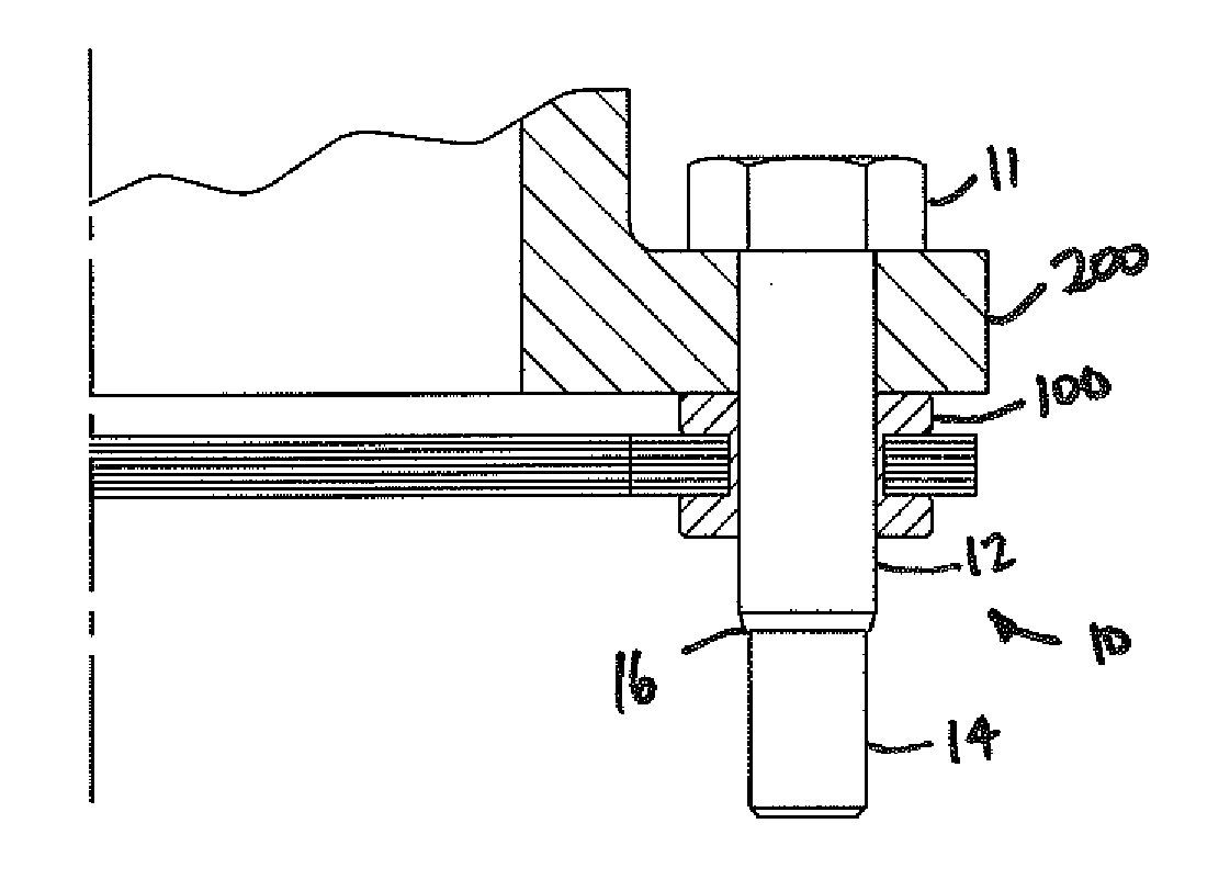
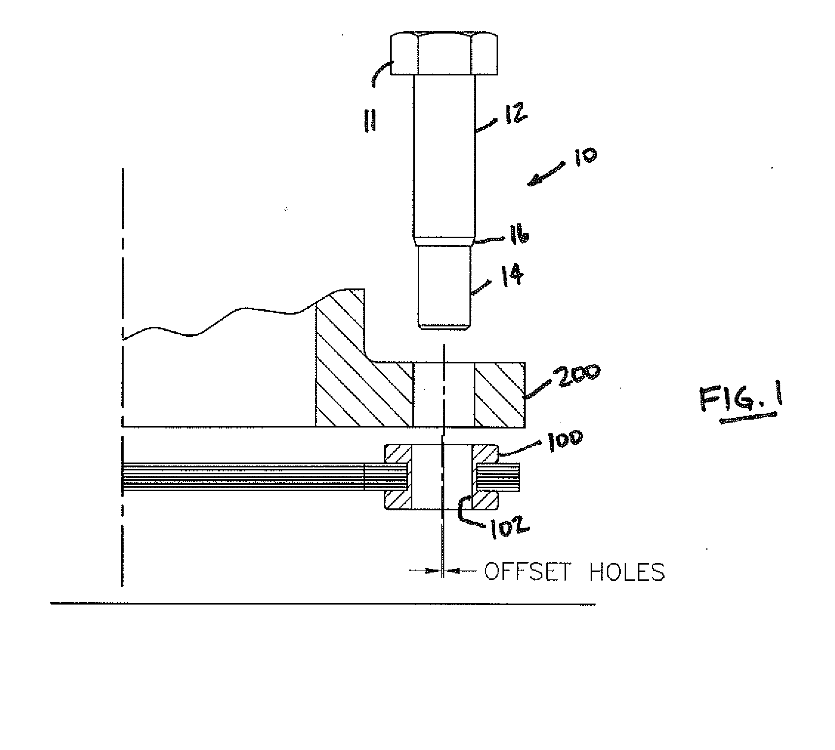
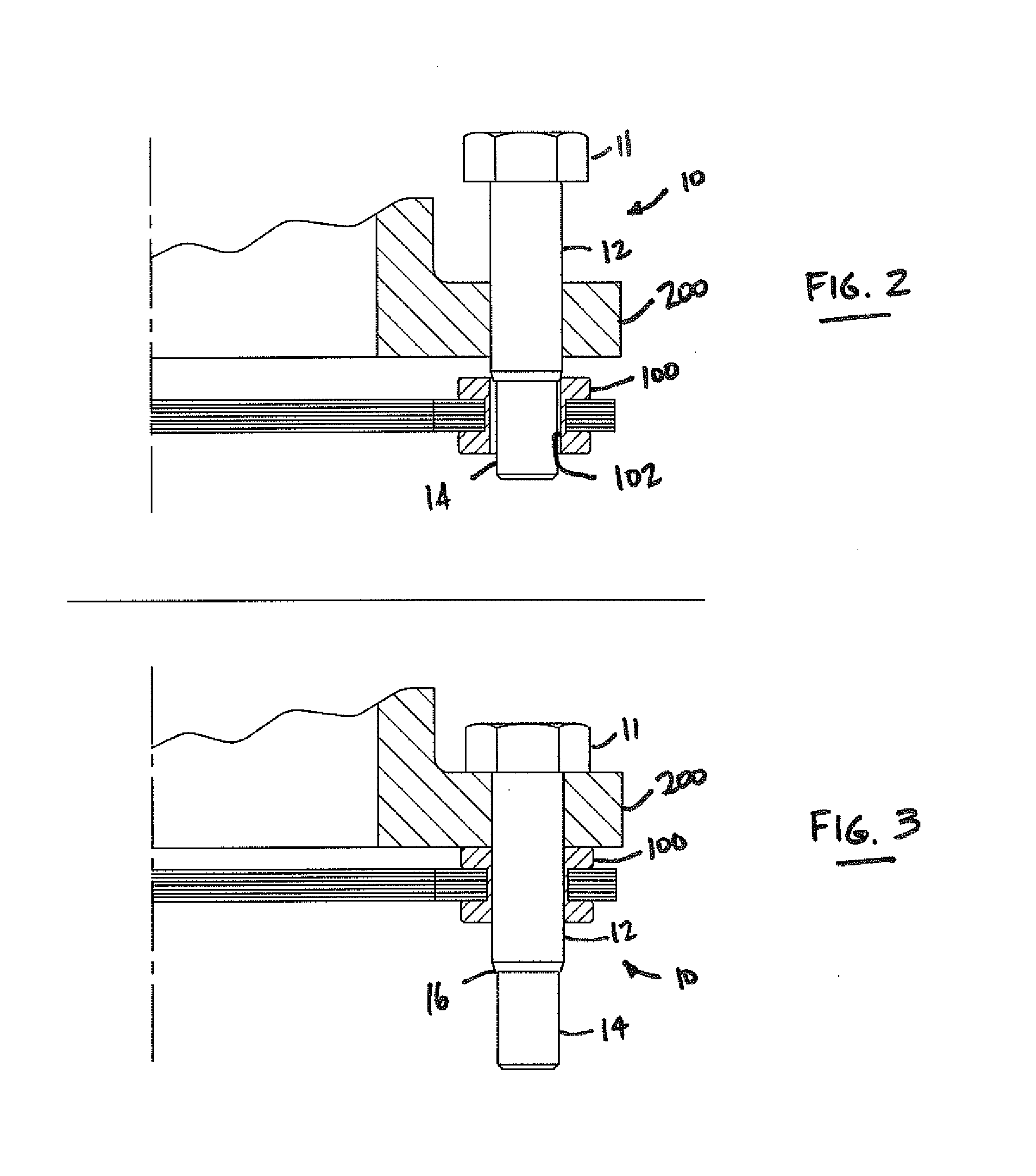
[0028]In some embodiments, threaded second diameter section 14 of
fastener 10 is designed to be sufficiently smaller than the unthreaded first diameter section 12 of fastener 10 to ensure that threaded second diameter section 14 does not make contact with the through-holes 102 in flexible element 100 during
assembly or disassembly. This provides the
advantage of protecting the threads on threaded second diameter section 14 of fastener 10 during assembly and disassembly.
[0029]It should be appreciated that the smaller diameter of threaded second diameter section 14 of fastener 10 provides an additional benefit in that a lower tightening torque is required (because of the reduced outside diameter relative to single diameter fasteners). This is advantageous in that smaller tooling requirements are required and, thus, safety can be improved. Moreover, less force is required by the installer during installation.
[0031]Still referring to FIGS. 1-5, in some embodiments tapered, transition section 16 of fastener 10 can be configured and sized to make first contact with the holes 102 in flexible element 100 and to facilitate assembly. The tapered, transition section 16 can begin just past threaded second diameter section 14. In this way, the tapered contour of transition section 16 can provide a smooth transition to permit holes 102 of flexible element 100 to contact this camming surface and be properly positioned on unthreaded first diameter section 12. Generally, a taper of less than 45 degrees would be advantageous in providing a smooth transition. As mentioned above, in this way, the threads are protected by avoiding contact during assembly and disassembly. Another
advantage of this design is that the taper aligns the flex element with the
mating component as fastener 10 is assembled through both, which makes assembly easier for the installer. Further, the taper facilitates assembly in the case where the holes in the two components are misaligned, either simply due to tolerances or intentionally by design, minimizing the force required to assemble fastener 10s.
[0032]With particular reference to FIGS. 5-6, in some embodiments, fastener 10 can comprise a thread cover 20 disposed over threaded second diameter section 14 to protect the threads thereof during shipment, handling, assembly, disassembly, and the like. The shape further facilitates installation in the case where the holes are not initially well-aligned in addition to being designed for pre-tension. Thread cover 20, in some embodiments, can comprise a sheath-like member being made of a predetermined material sufficient to protect the threads, such as plastic, having a tip portion 22 protecting the end 26 of fastener 10 and a sheath portion 24 generally surrounding the threads. Thread cover 20 can terminate at an end 28 that is generally adjacent transition section 16 of fastener 10.
[0034]Generally, it should be understood that the principles of the present teachings provide a number of advantages over the prior art. Specifically, it should be recognized that the present teachings can be used in any assembly where two components have offset holes either by design or through tolerance buildup, thereby replacing tapered alignment pins.

