

Two-part liquid cleaner system
- Summary
- Abstract
- Description
- Claims
- Application Information
AI Technical Summary
Benefits of technology
Problems solved by technology
Method used
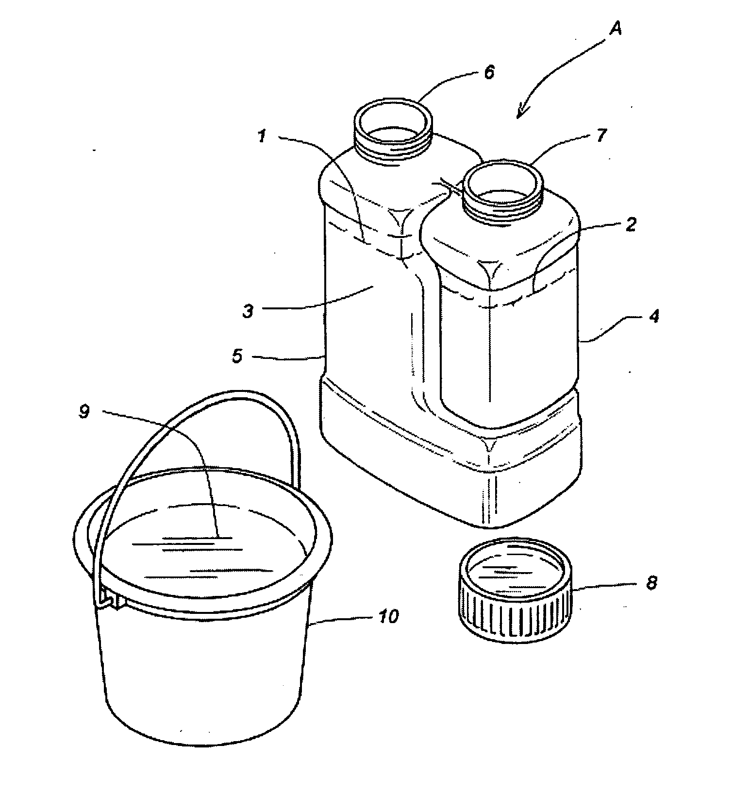
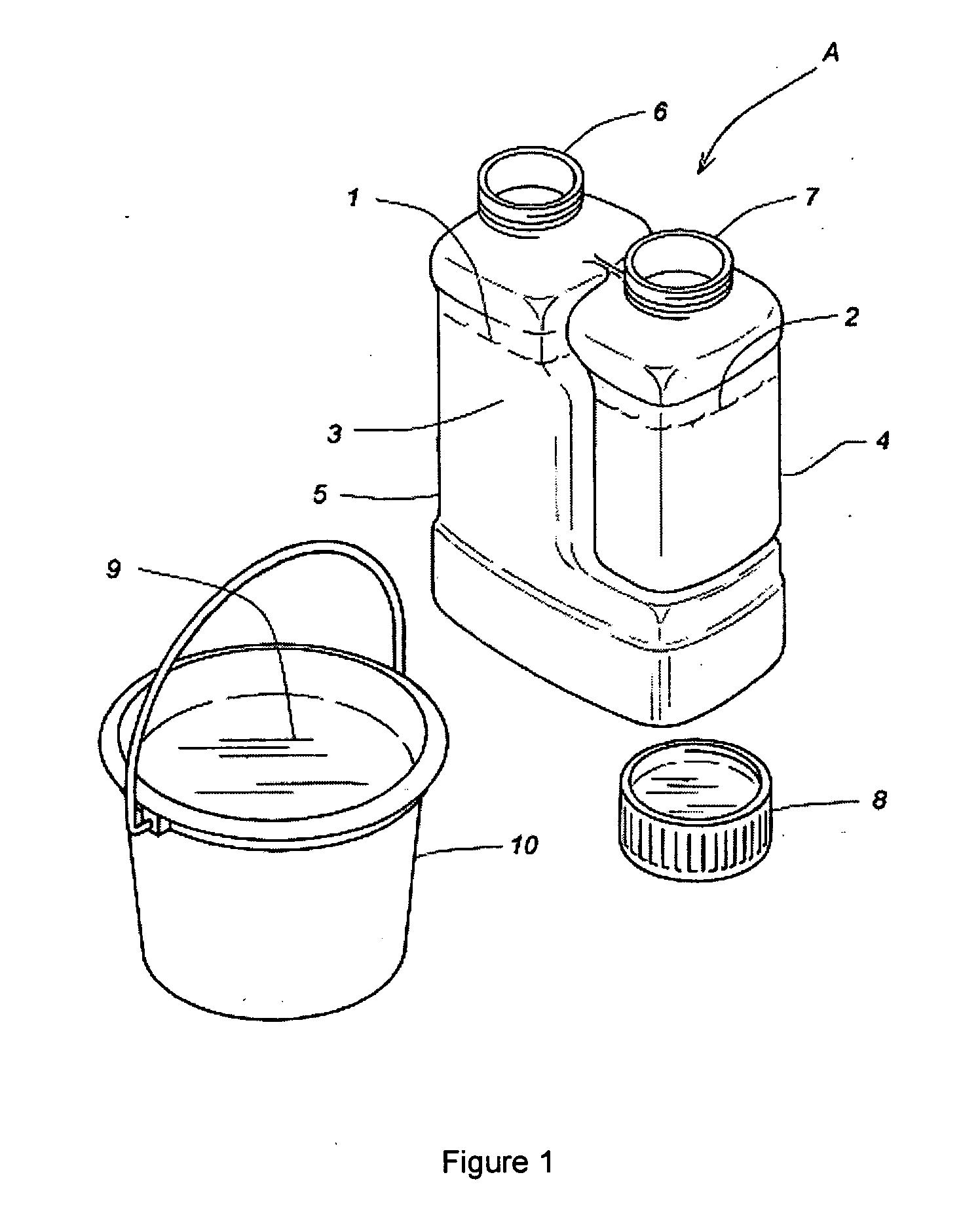
Image

Examples
Embodiment Construction
[0028]In general, liquid HVAC coil cleaners contain certain primary components to be effective. More specifically, liquid HVAC coil cleaners generally contain a metal-reactive component such as an acid or alkaline ingredient, a surfactant, a chelating agent, a thickening agent (optional), and a foam builder / stabilizer (optional). Those of skill in the art will be familiar with each of these components.
[0029]The metal-reactive component is used to release the binding that debris build-up may have on the metal surfaces of the HVAC coil. It is used to loosen the debris so that the debris can then be manipulated by other components of the HVAC coil cleaner. Common acidic metal-reactive ingredients include some form of hydrofluoric acid or ammonium biflouride (ammonium hydrogendifluoride). Common alkaline metal-reactive agents include some forms of sodium hydroxide (also known as “caustic soda”) or potassium hydroxide (also known as “potash”). Typical metal-reactive components, as well a...
PUM
 Abstract
Description
Claims
Application Information