Endoluminal vascular prosthesis

a vascular prosthesis and endoluminal technology, applied in the field of endoluminal vascular prosthesis, can solve the problems of high mortality, abdominal wall surgery, sac rupture, etc., and achieve the effect of high risk, and reducing the risk of surgery

Inactive Publication Date: 2011-09-08
ENDOLOGIX LLC
View PDF109 Cites 29 Cited by
  • Summary
  • Abstract
  • Description
  • Claims
  • Application Information

AI Technical Summary

Benefits of technology

[0022]The first support can span the vessel branch to make contact with the vessel wall on the opposing side of the vessel branch. One or more distal apices of the first support can be longitudinally offset from other distal apices of the first support, and one or more distal apices of the second support can be longitudinally offset from other distal apices of the second support. Further, without limitation, each of the distal apices of the second support can be circumferentially offset from each of the proximal apices of the first support. In any of the embodiments disclosed herein, one or more of the distal apices of the second support can be approximately circumferentially aligned with each of the proximal apices of the first support.

Problems solved by technology

When left untreated, the aneurysm may eventually cause rupture of the sac with ensuing fatal hemorrhaging in a very short time.
High mortality associated with the rupture led initially to transabdominal surgical repair of abdominal aortic aneurysms.
Surgery involving the abdominal wall, however, is a major undertaking with associated high risks.
There is considerable mortality and morbidity associated with this magnitude of surgical intervention, which in essence involves replacing the diseased and aneurysmal segment of blood vessel with a prosthetic device which typically is a synthetic tube, or graft, usually fabricated of polyester, urethane, Dacron®, Teflon®, or other suitable material.
Thus, if the patient is not receiving routine examinations, it is possible that the aneurysm will progress to the rupture stage, wherein the mortality rates are significantly higher.
Disadvantages associated with the conventional, prior art surgery, in addition to the high mortality rate include the extended recovery period associated with such surgery; difficulties in suturing the graft, or tube, to the aorta; the loss of the existing aorta wall and thrombosis to support and reinforce the graft; the unsuitability of the surgery for many patients having abdominal aortic aneurysms; and the problems associated with performing the surgery on an emergency basis after the aneurysm has ruptured.
Since the graft must typically be secured, or sutured, to the remaining portion of the aorta, it is many times difficult to perform the suturing step because the thrombosis present on the remaining portion of the aorta, and that remaining portion of the aorta wall may be friable, or easily crumbled.
Since many patients having abdominal aortic aneurysms have other chronic illnesses, such as heart, lung, liver, and / or kidney disease, coupled with the fact that many of these patients are older, the average age being approximately 67 years old, these patients are not ideal candidates for such major surgery.
When this occurs, it may be detrimental to implant a conventional tubular graft in this location of the aorta or the blood vessel, since such a graft may obstruct the flow of blood from the aorta into the branches.
Additionally, properly located deployment of prosthetic grafts adjacent branches in the aorta present risks of flow obstruction in the branch vessels because identifying the distal ends of the grafts can be difficult under fluoroscopy.
Leakage of blood flow between the graft and the blood vessel tissue can risk further deterioration of the diseased aneurysm.
This can be specifically challenging in infrarenal aneurysms where the proximal seal zone below the renal arteries is often short, angulated, and calcified.

Method used


Image

  • Endoluminal vascular prosthesis
  • Endoluminal vascular prosthesis
  • Endoluminal vascular prosthesis

Examples


Embodiment Construction

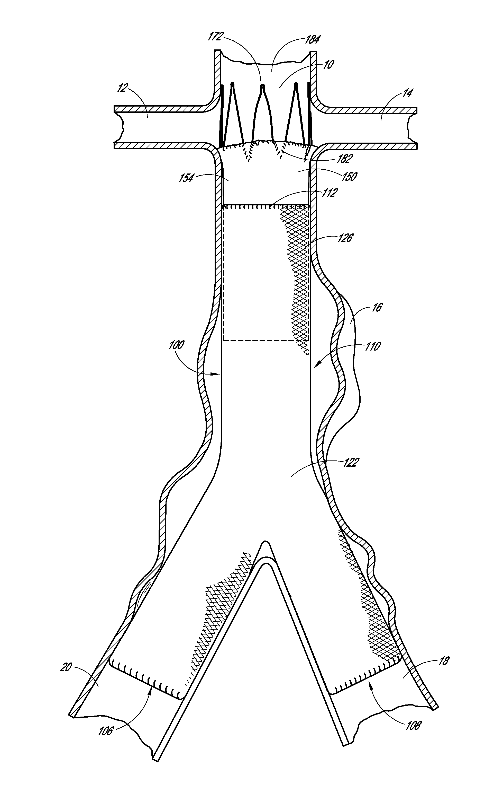
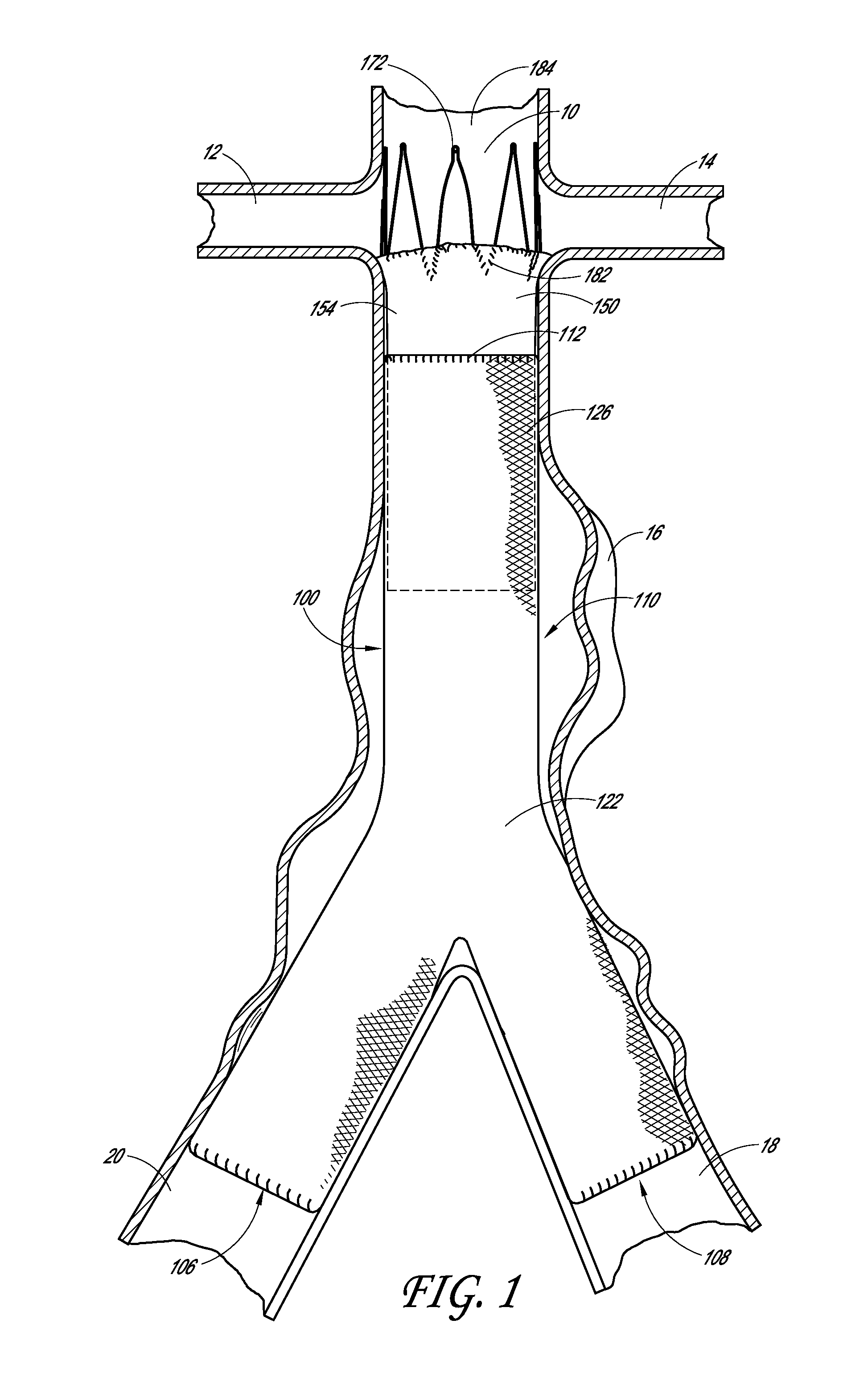
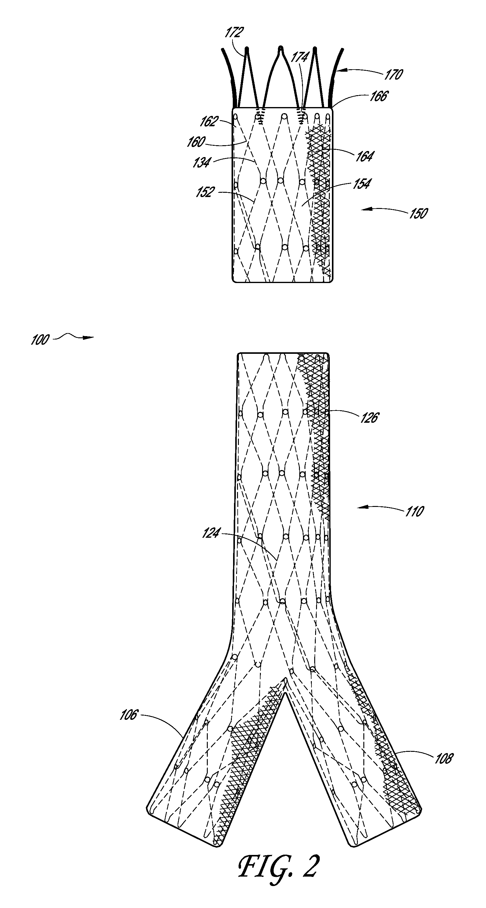
[0016]Some embodiments comprise an endoluminal prosthesis that can include a first support having a proximal end and a distal end and a second support having a proximal end and a distal end. The second support can be located closer to a proximal end of the prosthesis as compared to the first support. A cover at least substantially covers the first support and at least a portion of the second support. At least a portion of each of the first and second supports can be coupled to the cover. The second support comprises distal apices that can be longitudinally and / or circumferentially offset as compared to proximal apices of the first support.

[0017]Some embodiments are directed to a method of deploying an endoluminal prosthesis in vasculature. The method includes inserting an endoluminal prosthesis within the vasculature. The endoluminal graft has a first support and a second support coupled to a sleeve. The second support can be coupled to a distal end of the sleeve and extends longitu...


PUM


Abstract

Some embodiments of an endoluminal prosthesis comprise a graft having a first end and a second end, a first stent positioned at a first end of the graft, the first stent comprising a plurality of proximal apices and a plurality of distal apices, a second stent positioned axially adjacent to the first stent comprising a plurality of proximal apices positioned at a first end of the second stent. In some embodiments, the first stent can be partially covered by the graft such that the proximal apices of the first stent are not covered by the graft. The distal apices of the first stent can be positioned approximately on a first or a second plane offset from the first plane. The second stent can be positioned relative to the first stent such that the plurality of proximal apices of the second stent are spaced apart from the plurality of distal apices of the first stent. Further, one or more of the proximal apices of the second stent can be positioned approximately on a third or a fourth plane. The distal apices of the first stent can be circumferentially offset from the proximal apices of the second stent.

Description

PRIORITY INFORMATION AND INCORPORATION BY REFERENCE[0001]This application claims priority benefit of U.S. Provisional Application 61 / 309,797 (titled “ENDOLUMINAL VASCULAR PROSTHESIS”), filed Mar. 2, 2010, which application is hereby incorporated by reference in its entirety as if fully set forth herein. The benefit of priority is claimed under the appropriate legal basis including, without limitation, under 35 U.S.C. §119(e).[0002]Additionally, U.S. Pat. No. 6,733,523, filed on Jun. 26, 2001, U.S. Pat. No. 6,077,296, filed on Mar. 4, 1998, and U.S. Provisional Patent Application No. 61 / 231,898, filed on Aug. 6, 2009 are hereby incorporated by reference in their entireties as if fully set forth herein.TECHNICAL FIELD[0003]The present disclosure relates to endoluminal vascular prostheses, and, in certain embodiments, to endoluminal vascular prostheses for use in the treatment of abdominal aortic aneurysms.BACKGROUND OF THE DISCLOSURE[0004]An abdominal aortic aneurysm is a sac caused b...

Claims


Application Information

Patent Timeline
Patent Type & Authority Applications(United States)
IPC IPC(8): A61F2/82
CPCA61F2/82A61F2/07A61F2250/0063A61F2002/075A61F2250/0039A61F2220/0075A61F2/89A61F2230/0054A61F2/915A61F2250/0098A61F2/852
Inventor NGUYEN, JONATHONMACIAS, JACQUELINETZENG, ELBERTSCHRECK, STEFAN
Owner ENDOLOGIX LLC
Why Eureka
Try Eureka