
Method and Apparatus for Optimizing the Performance of a Storage System

a storage system and performance optimization technology, applied in the field of storage system performance optimization, can solve the problems of failures that can often be traced, hard disc drives subject to regular use are prone to failure, and hard disc drives that are subject to regular use are often relatively slow in terms of read/write performance, so as to promote sequential write operations and optimize the performance of storage systems.

Inactive Publication Date: 2011-09-08
IBM CORP
View PDF16 Cites 203 Cited by
  • Summary
  • Abstract
  • Description
  • Claims
  • Application Information

AI Technical Summary

Benefits of technology

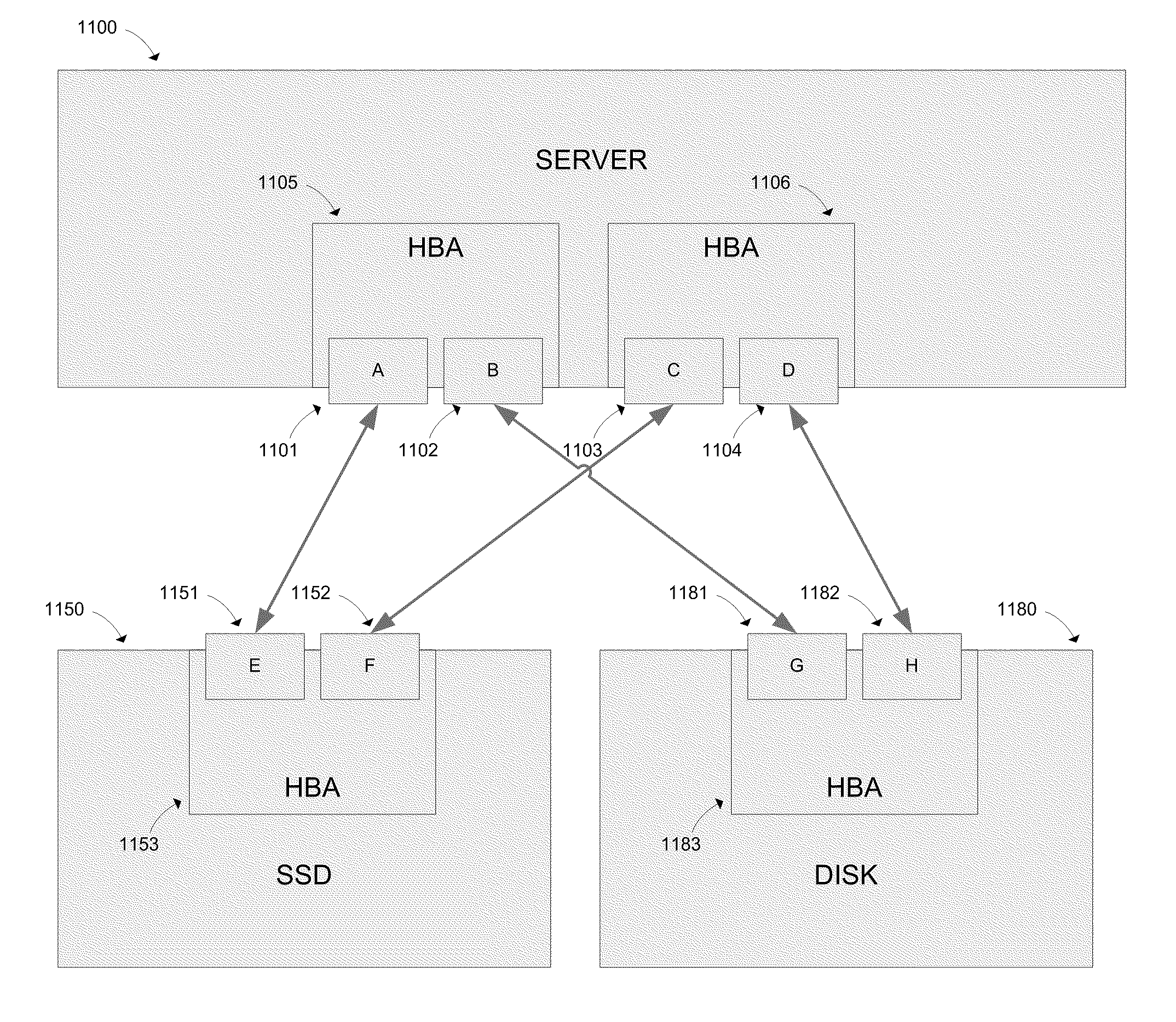
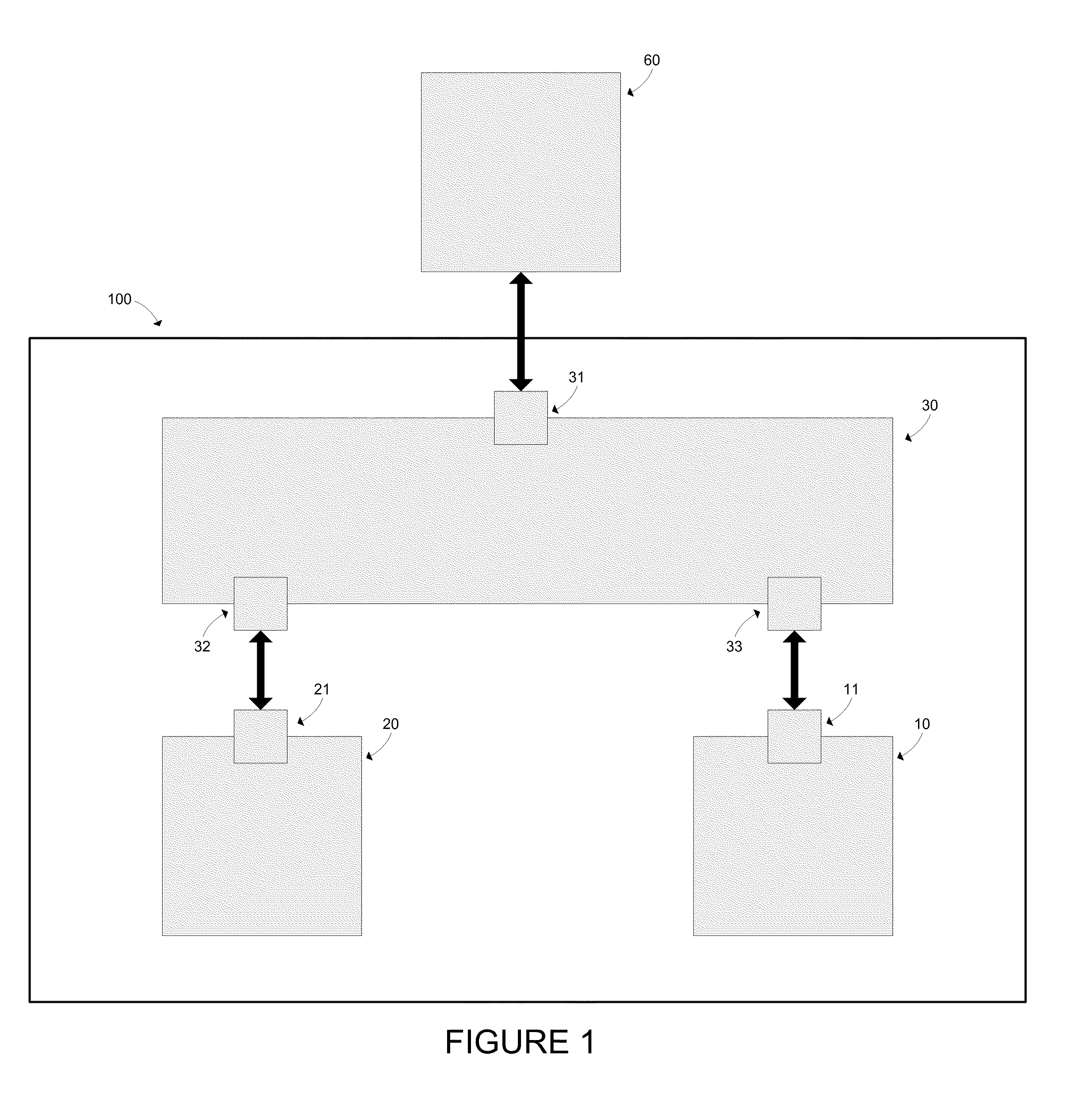
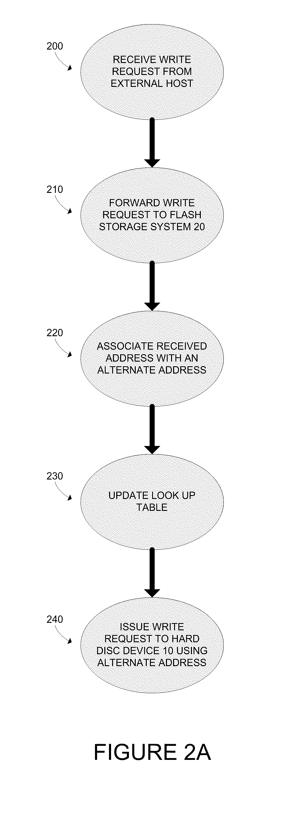
[0011]The disclosed embodiments are directed to methods and apparatuses for optimizing the performance of a storage system. In some implementations, the disclosed embodiments involve a storage system for processing READ and WRITE requests from an external host. Such a storage system may comprise a FLASH storage system, a hard drive storage system, and a storage controller. The storage controller is adapted to receive READ and WRITE requests from an external host, and is coupled to the FLASH storage system and the hard drive storage system such that the storage controller can issue READ and WRITE requests to both the FLASH storage system and the hard drive storage system. In general operation, the storage controller receives a WRITE request from an external host, the WRITE request containing data and an address corresponding to a location where such data is to be stored. The storage controller then forwards the received WRITE request to the FLASH storage system and associates the address provided in the WRITE request with a selected alternative address, and provide an alternative WRITE request to the hard drive storage system, wherein the alternative WRITE request includes the selected alternative address and the data received in the WRITE request, and wherein the alternative address is selected to promote sequential WRITE operations within the hard drive storage system. The storage controller also receives a READ request from an external host, the READ request containing an address corresponding to a location from which data is to be read. The storage controller thereafter forwards the received READ request to the FLASH storage system, returns the data received from the FLASH storage system to the external host in the absence of a READ error from the FLASH storage system, or issues an alternative READ request to the hard drive storage system, the alternative READ request containing an address corresponding to an alternative address associated by the storage controller with the address received from the external host in the READ request and returning the data received from the hard drive storage system to the external host in the event of a READ error from the FLASH storage system.

Problems solved by technology

There are, however, several drawbacks associated with hard disc drives.
First, hard disc drives are often relatively slow in terms of their read / write performance when compared to other types of available storage media (such as FLASH memory).
Second, hard disc drives that are subject to regular use are prone to failure.
Such failures can often be traced to movement of the mechanical members within the disc drives, such as the head and arm.
Such “seeking” can result in failure of the physical mechanisms within a hard disc drive.
However, FLASH storage has drawbacks which have limited its widespread use.
A first drawback is performance.
The least expensive form of FLASH memory, multi-level cell (MLC) FLASH memory, is subject to rapid degradation such that the operation of such devices is prone to error.
A second drawback is cost.
Such SLC FLASH memory is, however, substantially more expensive than both hard disc memory and MLC FLASH memory.
As such, the cost issues associated with SLC FLASH memory have limited its widespread adoption in many enterprise applications.

Method used


Image

  • Method and Apparatus for Optimizing the Performance of a Storage System
  • Method and Apparatus for Optimizing the Performance of a Storage System
  • Method and Apparatus for Optimizing the Performance of a Storage System

Examples


Embodiment Construction

[0026]The Figures described above and the written description of specific structures and functions below are not presented to limit the scope of what Applicants have invented or the scope of the appended claims. Rather, the Figures and written description are provided to teach any person skilled in the art to make and use the inventions for which patent protection is sought. Those skilled in the art will appreciate that not all features of a commercial embodiment of the inventions are described or shown for the sake of clarity and understanding. Persons of skill in this art will also appreciate that the development of an actual commercial embodiment incorporating aspects of the present inventions will require numerous implementation-specific decisions to achieve the developer's ultimate goal for the commercial embodiment. Such implementation-specific decisions may include, and likely are not limited to, compliance with system-related, business-related, government-related and other c...


PUM


Abstract

Methods and apparatuses for optimizing the performance of a storage system comprise a FLASH storage system, a hard drive storage system, and a storage controller. The storage controller is adapted to receive READ and WRITE requests from an external host, and is coupled to the FLASH storage system and the hard drive storage system. The storage controller receives a WRITE request from an external host containing data and an address, forwards the received WRITE request to the FLASH storage system and associates the address provided in the WRITE request with a selected alternative address, and provides an alternative WRITE request, including the selected alternative address and the data received in the WRITE request, to the hard drive storage system, wherein the alternative address is selected to promote sequential WRITE operations within the hard drive storage system.

Description

CROSS REFERENCE TO RELATED APPLICATIONS[0001]Not Applicable.STATEMENT REGARDING FEDERALLY SPONSORED RESEARCH[0002]Not applicable.REFERENCE TO APPENDIX[0003]Not applicable.BACKGROUND OF THE INVENTION[0004]1. Field of the Invention[0005]This disclosure relates generally to methods and apparatuses for optimizing the performance of a storage system for storing digital data.[0006]2. Description of the Related Art[0007]Hard disc drives have conventionally been used to store digital data in enterprise systems. One of the reasons for this extensive use of hard disc drives is that hard disc drive storage has often been the lowest cost storage medium suitable for such applications. There are, however, several drawbacks associated with hard disc drives. First, hard disc drives are often relatively slow in terms of their read / write performance when compared to other types of available storage media (such as FLASH memory). Second, hard disc drives that are subject to regular use are prone to fai...

Claims


Application Information

Patent Timeline
Patent Type & Authority Applications(United States)
IPC IPC(8): G06F12/00G06F12/02
CPCG06F12/00G06F12/02G06F3/0679G06F3/0655G06F3/061G06F12/0246G06F3/0616G06F3/0631G06F3/0659G06F3/067G06F3/068G06F12/0638G06F2212/1036G06F2212/154G06F2212/214G06F2212/261G06F2212/70G06F2212/7202
Inventor FROST, HOLLOWAY H.SCHEEL, DANIEL E.
Owner IBM CORP
Learn More