
Systems and methodologies for proton computed tomography

Active Publication Date: 2011-09-15
UNIVERSITY OF HAIFA +2
View PDF91 Cites 64 Cited by
  • Summary
  • Abstract
  • Description
  • Claims
  • Application Information

AI Technical Summary

Benefits of technology

[0023]For purposes of summarizing the disclosure, certain aspects, advantages and novel features of the inventions have been described herein. It is to be understood that not necessarily all such advantages may be achieved in accordance with any particular

Problems solved by technology

Reconstruction of 2-dimensional images from protons that pass through such an object can be difficult due to a relatively large number of protons involved and the different types of interactions that protons undergo within the object.

Method used


Image

  • Systems and methodologies for proton computed tomography
  • Systems and methodologies for proton computed tomography
  • Systems and methodologies for proton computed tomography

Examples


example 1

[0141]The foregoing example DROP based superiorization technique can be implemented in a number of ways. In a first example, an initial image estimate for subsequent iterative procedure can be acquired by performing a filtered backprojection (FBP) reconstruction from the measured data. Such a FBP can be carried out by rebinning individual proton histories to substantially conform with a known sonogram grid. For the iterative procedure, the DROP projection operator can be applied cyclically until all blocks of the data set is processed. In some implementations, an optional feasibility proximity calculation as described herein can be checked including substantially all histories in the data set.

[0142]In some implementations, the foregoing first example DROP based total variation superiorization technique can be coded in a number of ways. For example, such a coding can include an algorithm such as:

 (1) set k=0 (2)set xk = xFBP an initial FBP reconstruction, and βk = 1 (3)repeat for N c...

example 2

[0143]In a second example, the DROP projection operator can be applied to a given block before continuing to an optional feasibility proximity check that is performed with histories from the subsequent block. Such an approach can be utilized when each block includes a substantially equal number of histories from each projection angle and thus can represent the data as a whole. Similar to the first example, an initial image estimate can be acquired by performing a filtered backprojection (FBP) reconstruction from the measured data.

[0144]In some implementations, the foregoing second example DROP based total variation superiorization technique can be coded in a number of ways. For example, such a coding can include an algorithm such as:

 (1)set k=0 (2)set xk = xFBP an initial FBP reconstruction, and βk = 1 (3)repeat for each block over N cycles (4) set s to a subgradient of φ at xk (5) if ||s|| > 0 set vk = −s / / ||s|| (6) else set vk = s (7) set continue = true (8) while continue (9)  se...

example 3

[0145]In a third example, the first example method can be modified such that the feasibility proximity check of step 12 is not performed. Such a modification may be desirable if a given feasibility proximity check is computationally demanding.


PUM


Abstract

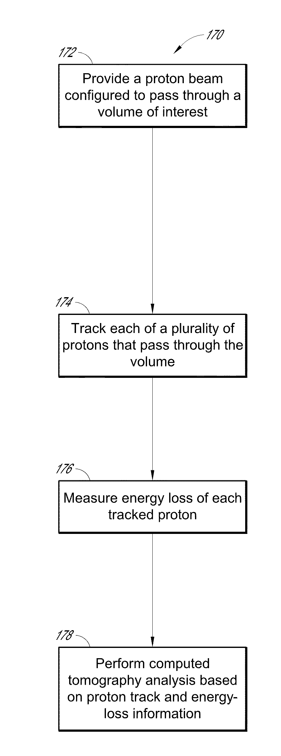
Disclosed are systems, devices and methodologies relating to proton computed tomography. In some implementations, detection of protons can yield track information before and after an object for each proton so as to allow determination of a likely path of each proton within the object. Further, measurement of energy loss experienced by each proton allows determination that a given likely path results in a given energy loss. A collection of such data allows characterization of the object. In the context of energy loss, such a characterization can include an image map of relative stopping power of the object. Various reconstruction methodologies for obtaining such an image, including but not limited to superiorization of a merit function such as total variation, are disclosed. In some implementations, various forms of total variation superiorization methodology can yield excellent results while being computationally efficient and with reduced computing time. In some implementations, such a methodology can result in high quality proton CT images using relatively low dose of protons.

Description

PRIORITY CLAIM[0001]This application claims the benefit of priority under 35 U.S.C. §119(e) of U.S. Provisional Patent Application No. 61 / 303,783, entitled “PROTON COMPUTED TOMOGRAPHY,” filed Feb. 12, 2010, which is hereby incorporated herein by reference in its entirety to be considered part of this specification.STATEMENT REGARDING FEDERALLY SPONSORED R&D[0002]This invention was funded, in part, by government support under NIH Grant No. R01HL070472 awarded by the National Heart, Lung, and Blood Institute. The government has certain rights in the invention.BACKGROUND[0003]1. Field[0004]The present disclosure generally relates to the field of medical imaging, and more particularly, to systems and methodologies for proton computed tomography.[0005]2. Description of the Related Art[0006]Computed tomography (CT) allows reconstruction of a specific physical property of a 3-dimensional object and arranges and displays this reconstruction as an array of 2-dimensional cross-sectional or “t...

Claims


Application Information

Patent Timeline
IPC IPC(8): G01N23/04G21K5/00G16B5/00
CPCG01N23/046A61N5/10A61N2005/1087G01N2223/419G06T11/003A61B6/4258A61B6/5205A61B6/583A61B6/032G06T11/006G16B5/00G16B40/00A61B6/4241A61B6/4266G01T1/17G01T1/2985
Inventor CENSOR, YAIRPENFOLD, SCOTT N.SCHULTE, REINHARD W.
Owner UNIVERSITY OF HAIFA
Learn More