Agile-Beam Radar Notably for the Obstacle 'Sense and Avoid' Function

a radar and antenna technology, applied in the field of antenna antenna 'sense and avoid' function, can solve the problems of difficult integration of electronics and antennas, tight electronics volume, and inability to achieve easy integration onto the carrier,

Active Publication Date: 2011-09-15
THALES SA
View PDF14 Cites 24 Cited by
  • Summary
  • Abstract
  • Description
  • Claims
  • Application Information

AI Technical Summary

Problems solved by technology

In addition to these technical constraints, the radar system must be able to be installed on various types of aircraft, and the constraints on volume for the electronics and surface area available for the antenna are very tight.
The challenge is thus to define a radar antenna architecture and an associated processing system allowing high-quality radiation patterns to be obtained, while at the same time minimizing the volume of the electronics and the antenna surface area to be installed.
Unfortunately, in order to guarantee an unambiguous spatial sampling over a wide area, the elementary sources forming the array must be separated from one another by a fraction of a wavelength.
Furthermore, such a solution would commandeer a continuous installation surface area of around 20 cm by 20 cm per antenna panel, which is not compatible with all carriers, especially as two panels are needed in o...

Method used


Image

  • Agile-Beam Radar Notably for the Obstacle 'Sense and Avoid' Function
  • Agile-Beam Radar Notably for the Obstacle 'Sense and Avoid' Function
  • Agile-Beam Radar Notably for the Obstacle 'Sense and Avoid' Function

Examples


Embodiment Construction

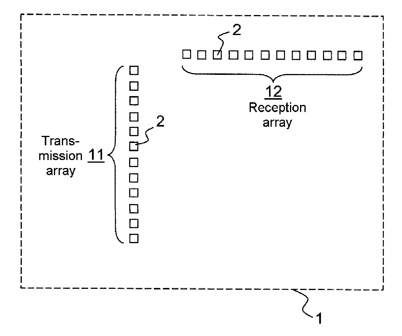
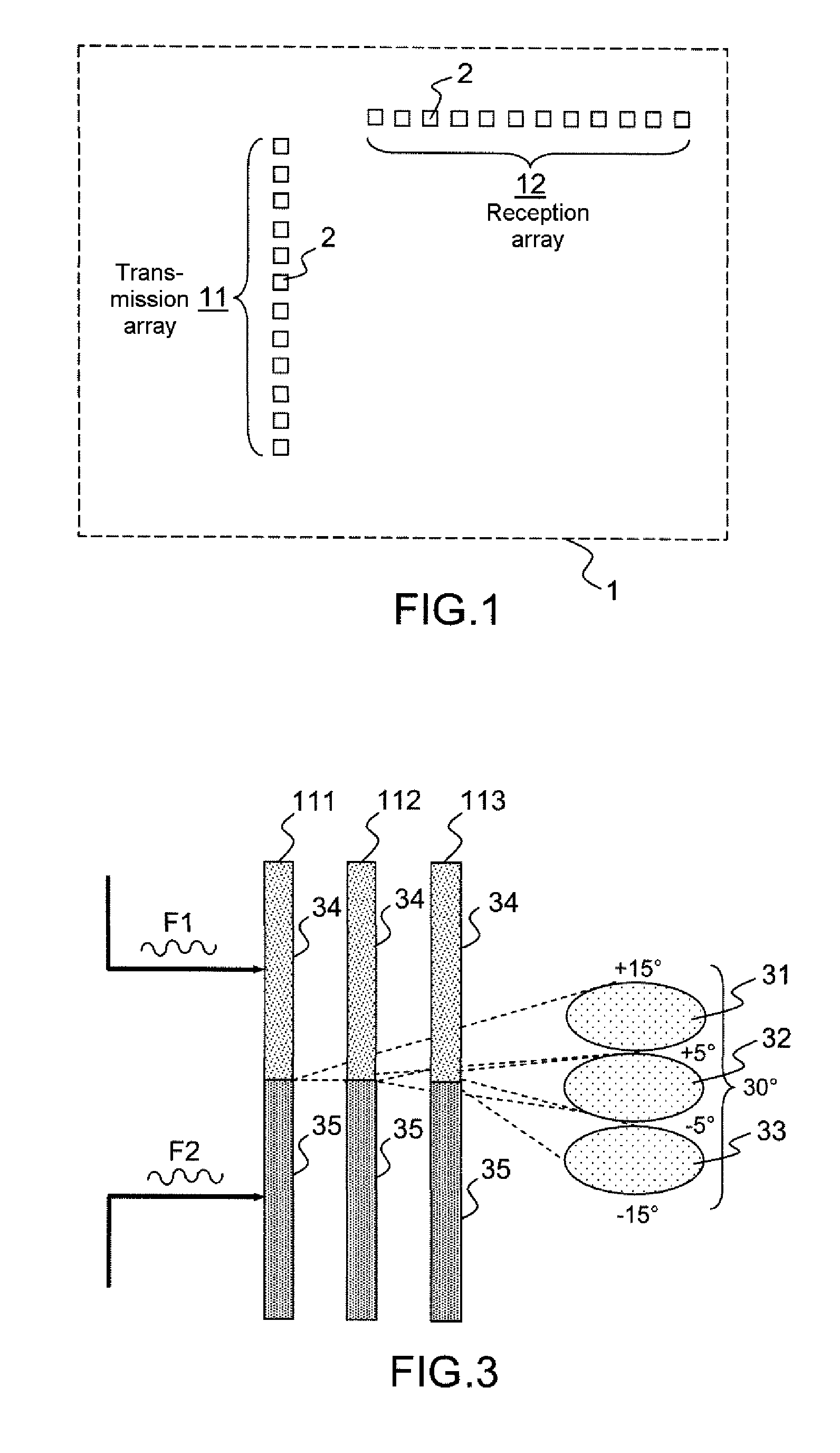
[0038]FIG. 1 shows the principle of construction of an antenna 1 used in a radar system according to the invention. This antenna comprises two arrays 11, 12 of radiating elements 2, each forming an elementary transmission source and an elementary reception receiver. They are fabricated using the same technology and are, for example, metal “patches”.

[0039]These two arrays 11, 12 are linear and orthogonal to one another. One array 11 is used for the transmission and the other array 12 is used for the reception. More particularly, the first array 11 is used to focus the antenna beam in one plane on transmission, using beam formation by computation. The second array 12 is used to focus the reception antenna beam in the plane orthogonal to the preceding plane, using beam formation by computation.

[0040]In view of the required respective angular ranges of coverage, + / −110° in azimuth and + / −15° in elevation, at least one vertical array is used for transmission and at least one horizontal a...


PUM


Abstract

A radar device includes an antenna having at least two linear arrays of radiating elements being orthogonal to one another, a first array being used to focus a transmission beam in a first plane and a second beam being used to focus a reception beam in a second plane, orthogonal to the first plane. The focussing of the beam is obtained in the first plane by coloured emission followed by a reception beam formation by computation, and in that the focussing of the beam is obtained in the second plane using reception beam formation by computation. The coloured emission is carried out by combining antenna transmission sub-arrays in such a manner as to form a sum channel and a difference on reception channel according to the monopulse technique.

Description

CROSS-REFERENCE TO RELATED APPLICATION[0001]This application claims priority to foreign French patent application No. FR 09 04395, filed on Sep. 15, 2009, the disclosure of which is incorporated by reference in its entirety.FIELD OF THE INVENTION[0002]The present invention relates to an agile-beam radar system. It is notably applicable for the obstacle detection and avoidance function, referred to as ‘sense and avoid’.BACKGROUND OF THE INVENTION[0003]The development of a non-cooperative airborne obstacle detection radar function for aircraft, in particular for drones, is essential in order to enable the insertion of autopiloted aircraft into unsegregated airspace. It participates in the obstacle detection and avoidance function known under the term “Sense and Avoid”.[0004]Such a radar system must be capable of a very wide field of observation, typically + / −110° in azimuth and + / −15° in elevation, and must be capable of scanning the airspace in a very short time, in view of the time ...

Claims


Application Information

Patent Timeline
IPC IPC(8): G01S13/93H01Q3/00G01S13/933
CPCG01S13/424G01S13/9303G01S13/48G01S13/4463G01S13/933
Inventor CORNIC, PASCALLE BIHAN, PATRICKKEMKEMIAN, STEPHANE
Owner THALES SA
Why Eureka
Try Eureka