Particle detection

a particle detection and particle technology, applied in the field of particle detection, can solve the problems of general inability to distinguish detectors, slow calibration, and type i (false positive) errors of beam detectors

a particle detection and particle technology, applied in the field of particle detection, can solve the problems of general inability to distinguish detectors, slow calibration, and type i (false positive) errors of beam detectors

US20110221889A1Active Publication Date: 2011-09-15GARRETT THERMAL SYST LTD

Image

  • Particle detection
  • Particle detection
  • Particle detection

Examples


Embodiment Construction

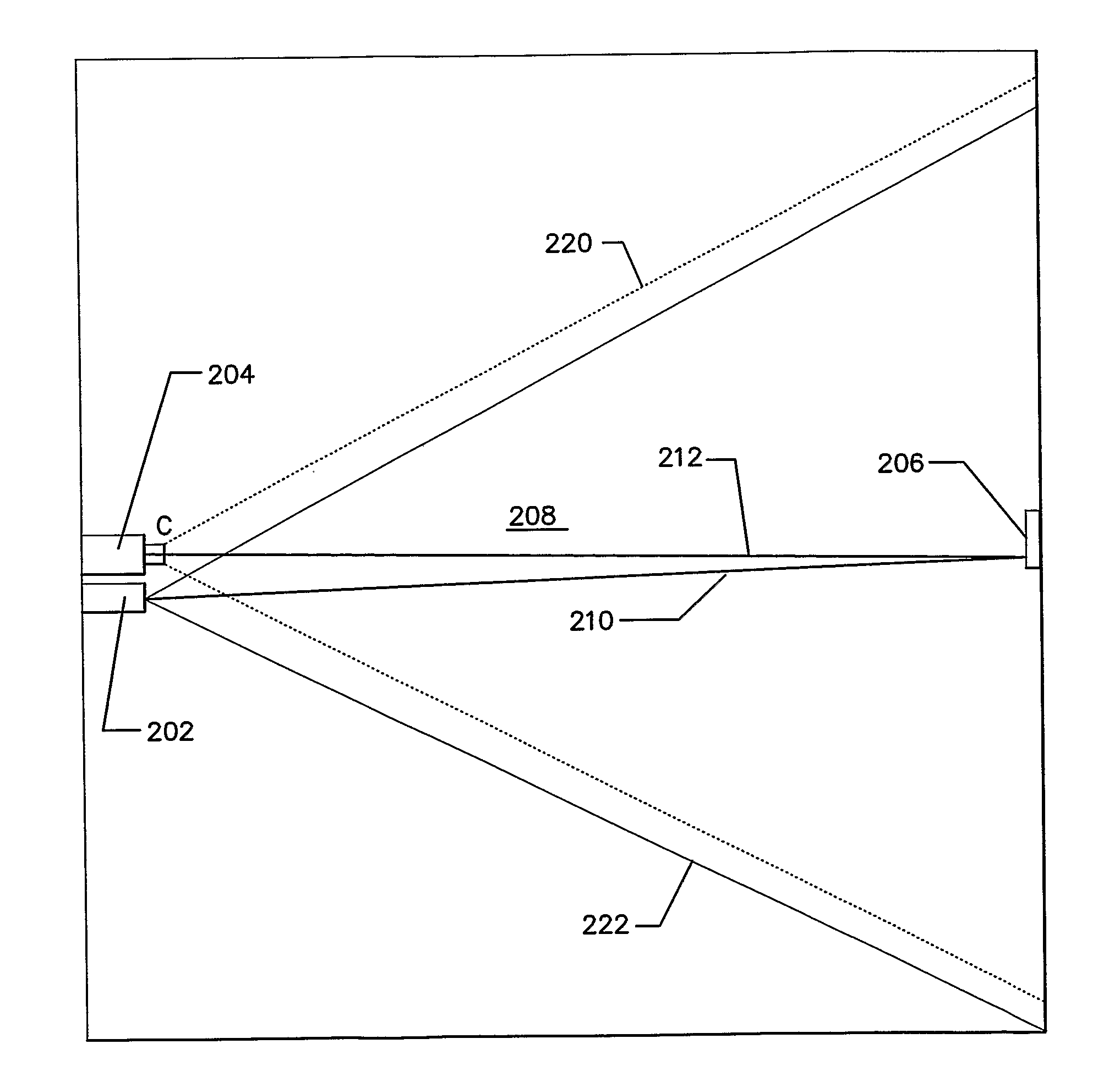
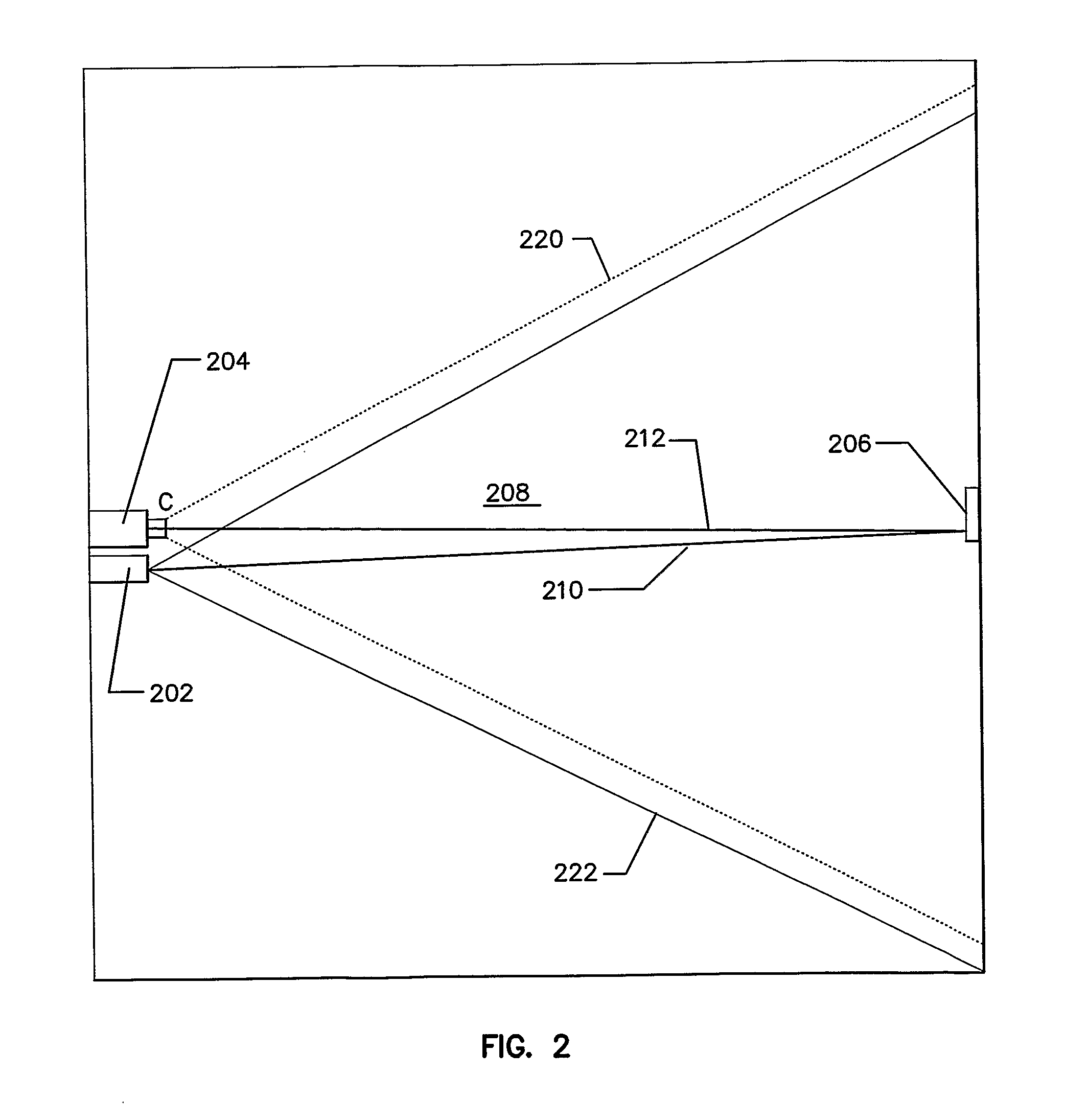
[0154]FIG. 2 shows an embodiment of the present invention. The detector 200 includes a light emitter 202, a receiver 204, and a target 206, acting in co-operation to detect particles in a monitored area 208. Target 206 reflects incident light 210 and thereby forms a light source and returns reflected light 212 to receiver 204. Preferably the target is a corner cube or other reflector adapted to reflect light back along its incident path, or other determined path.

[0155]The term light source as used is intended to be interpreted to include a device that actively produces an illumination from one or more (generally termed a light emitter or transmitter herein) as well as a reflector of an illumination generated by another device (generally termed a target or reflector herein).

[0156]In the preferred embodiment the receiver 204 is preferably a video camera or other receiver having an array of light sensors. A person skilled in the art would appreciate that receiver 204 may be constructed...


PUM


Abstract

A particle detection system including; at least one light source adapted to illuminate a volume being monitored at least two wavelengths; a receiver) having a field of view and being adapted to receive light from at least one light source after said light has traversed the volume being monitored and being adapted to generate signals indicative of the intensity of light received at regions within the field of view of the receiver; a processor associated with the receiver adapted to process the signals generated by the receiver to correlate light received at least two wavelengths in corresponding regions within the field of view of the receiver and generate an output indicative of the relative level of light received at the two wavelengths.

Description

FIELD OF THE INVENTION[0001]The present invention relates to particle detection. It will be convenient to hereinafter describe the invention in the context of smoke detection, however it should be appreciated that the present invention is not limited to that use.BACKGROUND OF THE INVENTION[0002]Various methods of detecting particles in air are known. One method of detecting the presence of particulate matter in air involves projecting a beam across a monitored area and measuring the attenuation of the beam. Such detectors are commonly known as ‘obscuration detectors’, or simply ‘beam detectors’.[0003]An exemplary, conventional beam detector is shown in FIG. 1. The detector 100 includes a light emitter and detector 102 and a reflector 104 placed either side of a monitored area 106. Incident light 108 from the light emitter and detector 102 are projected toward the reflector 104. The reflector 104 reflects the incident light 108 as reflected light 110. Reflected light 110 is reflected...

Claims


Application Information

Patent Timeline
15 Sep 2011
Publication
US20110221889A1
IPC
G01N21/00; H04N7/18
CPC
G01N21/53; G08B17/107; G01N21/538; G01N15/0205; G01N15/0227; G01N21/49; G01N2201/0627; G01N2201/062
Inventors
KNOX, RON; BOETTGER, KARL