Circularly polarizing plate and display device
a display device and polarizing plate technology, applied in the field of circular polarizing plate and a display device, can solve the problems of inability to achieve the reduction of reflection inside the liquid crystal cell, inability to apply conventional reflection reduction technologies, and small anti-reflective effect obtained by this method, etc., to achieve high contrast ratio, low cost, and superior visibility
- Summary
- Abstract
- Description
- Claims
- Application Information
AI Technical Summary
Benefits of technology
Problems solved by technology
Method used
Image
Examples
first embodiment
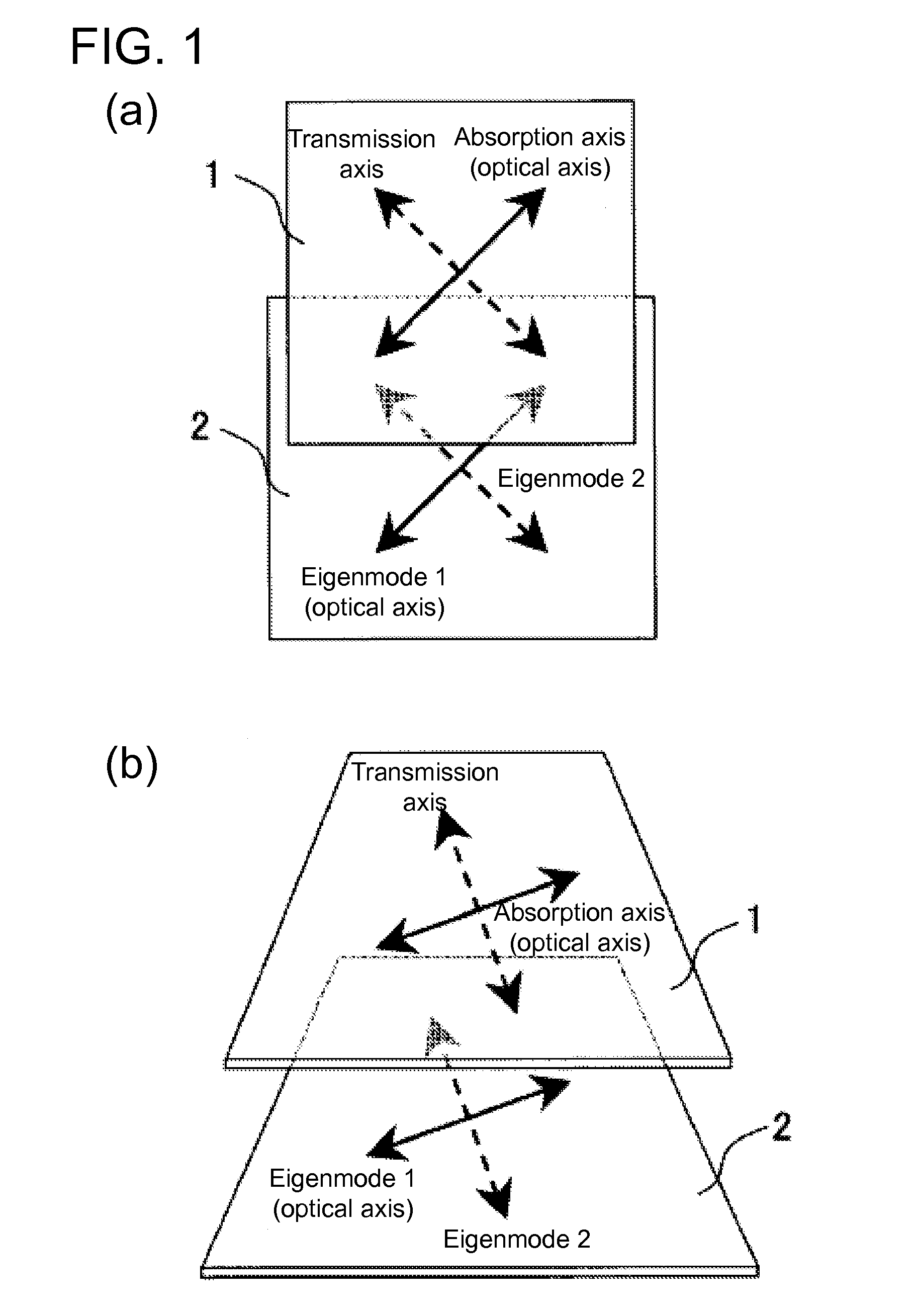
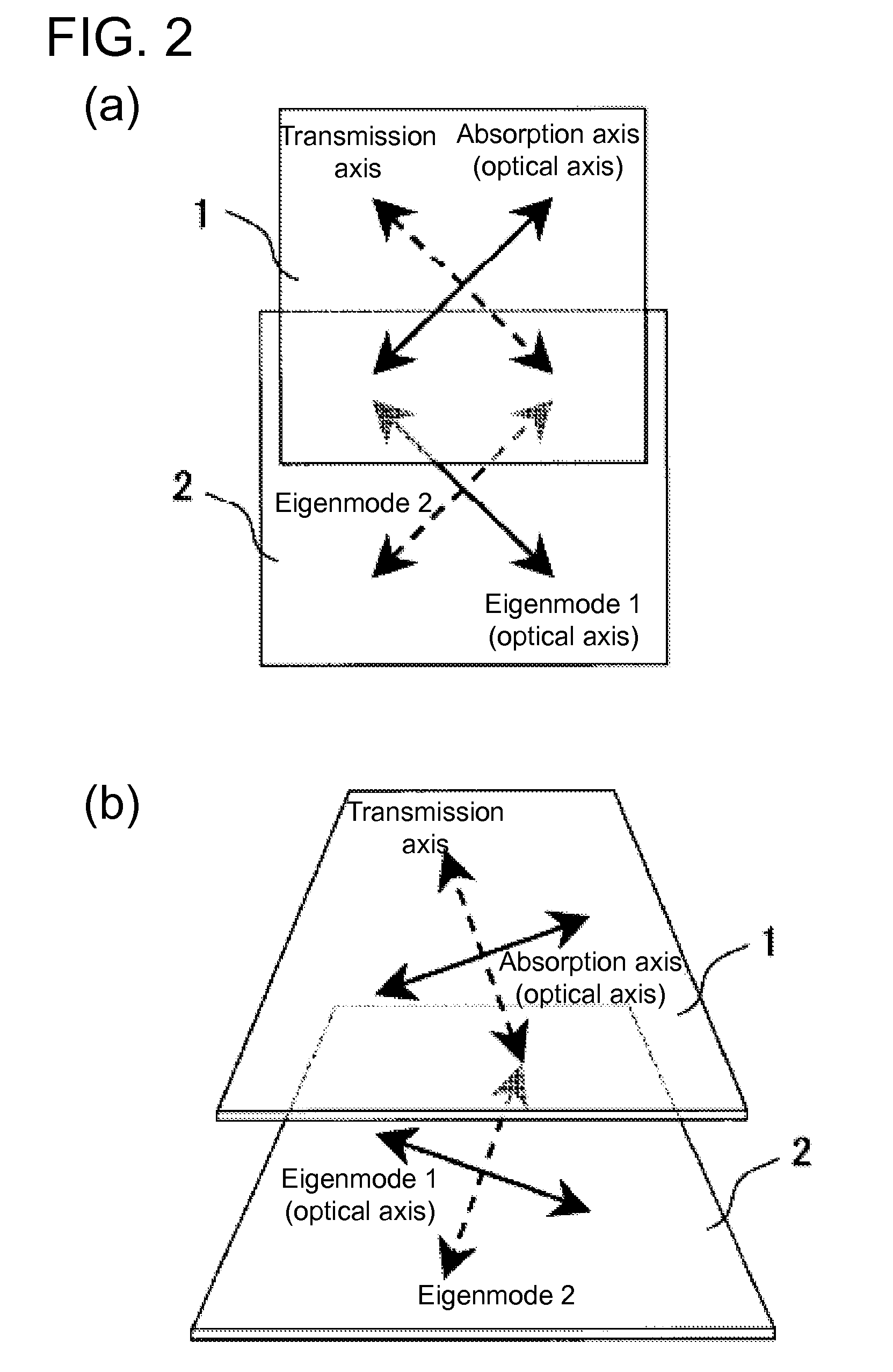
[0082]The circularly polarizing plate of the present embodiment includes an anti-reflective layer, a polarizer, a birefringent layer (also called birefringent layer A henceforth), and a λ / 4 plate (also called the λ / 4 plate B henceforth), which are laminated in this order. The NZ coefficient of the birefringent layer A satisfies NZ0.9, and the in-plane slow axis of the λ / 4 plate B intersects with the absorption axis of the polarizer.
[0083]The circularly polarizing plate of the present embodiment includes the polarizer and the λ / 4 plate B, the in-plane slow axis of which intersects with the absorption axis of the polarizer and, hence, functions as a so-called circular polarizer and is able to achieve an anti-reflective effect.
[0084]Furthermore, the circular polarizing plate of the present embodiment includes a birefringent layer A, the in-plane fast axis of which is orthogonal to the absorption axis of the polarizer, and hence is able to achieve an anti-reflective effect across a wide...
embodiment 1
[0135]Described below is a circularly polarizing plate of Embodiment 1 of the first embodiment. FIG. 6 is a cross-sectional schematic drawing showing the circularly polarizing plate of Embodiment 1.
[0136]An anti-reflective film 114, which has a moth eye structure, a linear polarizer 111, a birefringent layer 112, and a λ / 4 plate 113 were laminated in the order as shown in FIG. 6 to construct the circularly polarizing plate (circularly polarizing optical film) of Embodiment 1. The optical parameters, such as the axis angle and retardation value, of each film are shown in the figure. The direction of the absorption axis of the linear polarizer 111 was chosen to be at a 0° azimuth angle.
[0137]The anti-reflective mechanism of the circularly polarizing optical film of Embodiment 1 is described using the Poincare sphere. FIG. 7 is a schematic cross-sectional drawing showing the circularly polarizing plate of Embodiment 1 placed on an anti-reflective plate. FIG. 8 is a cross-sectional sche...
embodiment 2
[0172]Provided below is a description on a circularly polarizing plate of Embodiment 2 of the first embodiment. FIG. 22 is a cross-sectional schematic drawing showing a circularly polarizing plate of Embodiment 2 placed on a reflective plate. FIG. 23 is a cross-sectional schematic drawing showing an optically equivalent structure to that of FIG. 22. Optical parameters of each film, including the axis angle and retardation value, or the like, are shown in the figure. The absorption axis direction of the linear polarizer 111 is chosen to be at the 0° azimuth.
[0173]An anti-reflective film 114 having a moth eye structure, linear polarizer 111, birefringent layer 112, and λ / 4 plate 113 are laminated in the order shown in FIG. 22 to construct the circularly polarizing plate (circularly polarizing film) of Embodiment 2. The circularly polarizing plate of Embodiment 2 is placed on a reflective plate 116. Furthermore, as shown in FIG. 22, the optically equivalent structure to FIG. 22 include...
PUM
 Abstract
Description
Claims
Application Information
 - R&D
- Intellectual Property
- Life Sciences
- Materials
- Tech Scout
- Unparalleled Data Quality
- Higher Quality Content
- 60% Fewer Hallucinations
Browse by: Latest US Patents, China's latest patents, Technical Efficacy Thesaurus, Application Domain, Technology Topic, Popular Technical Reports.
© 2025 PatSnap. All rights reserved.Legal|Privacy policy|Modern Slavery Act Transparency Statement|Sitemap|About US| Contact US: help@patsnap.com


