Perpendicular recording magnetic head, manufacturing method thereof and magnetic disk drive

a technology of perpendicular recording and magnetic head, which is applied in the direction of recording head housing/shield, record information storage, instruments, etc., can solve the problems of destroying adjacent tracks, deteriorating recording performance, and increasing so as to increase the recording magnetic field, increase the accuracy of track width, and maintain the effect of track width

Inactive Publication Date: 2011-09-15
HITACHI LTD
View PDF8 Cites 30 Cited by
  • Summary
  • Abstract
  • Description
  • Claims
  • Application Information

AI Technical Summary

Benefits of technology

[0023](1) The main pole of the perpendicular recording magnetic head is formed of the first main pole portion having a bevel angle and formed in an inverse trapezoidal shape dealing with a skew angle, and the second main pole portion laminated on the first main pole portion, having no bevel angle and defining a fixed track width. Thus, a recording magnetic field can be increased.
[0024](2) The track portion of the second main pole portion has a tapered shape in the element-height direction and the tapered tip portion of the air bearing surface is controlled within the range of the second main pole. Therefore, even if the taper angle slightly varies, the track width is constant. Thus, the accuracy in the track width can be increased.
[0025](3) The perpendicular recording magnetic head is such that the main pole has the laminated structure of the first main pole portion and the second main pole portion. Therefore, even if the flare point is varied during the machining of the air bearing surface, the degree by which the area of the air bearing surface varies is smaller than that of the conventional art, i.e., the variation in effective track width can be reduced. Thus, superior recording performance can be provided.
[0026](4) The second main pole portion is etched in a tapered shape from the predetermined position of the flare portion to the tip of the second main pole portion. Thus, the magnetic flux can be concentrated on the tip of the main pole, thereby increasing a recording magnetic field.
[0027](5) According to the method of manufacturing a perpendicular recording magnetic head, the inorganic insulating film on the substrate is etched in a trench shape by RIE by use of the hard mask and the first main pole portion and the second main pole portion are subjected to continuous magnetic plating in the trench. Therefore, the first and second main pole portions can simultaneously be formed through self-alignment without individually forming the second main pole portion. Thus, the increasing of accuracy in the track width can be enabled, that is, the accuracy in the track width can be increased; therefore, yield can be improved.

Problems solved by technology

At that time, if a main pole has a rectangular air bearing surface, there arises a problem of erasing adjacent tracks.
In addition, increasing of accuracy in track width is also a major problem.
In contrast, the thinning of the main pole poses a major problem of deterioration in recording performance such as a reduction in field intensity or degradation in field gradient.

Method used


Image

  • Perpendicular recording magnetic head, manufacturing method thereof and magnetic disk drive
  • Perpendicular recording magnetic head, manufacturing method thereof and magnetic disk drive
  • Perpendicular recording magnetic head, manufacturing method thereof and magnetic disk drive

Examples


Embodiment Construction

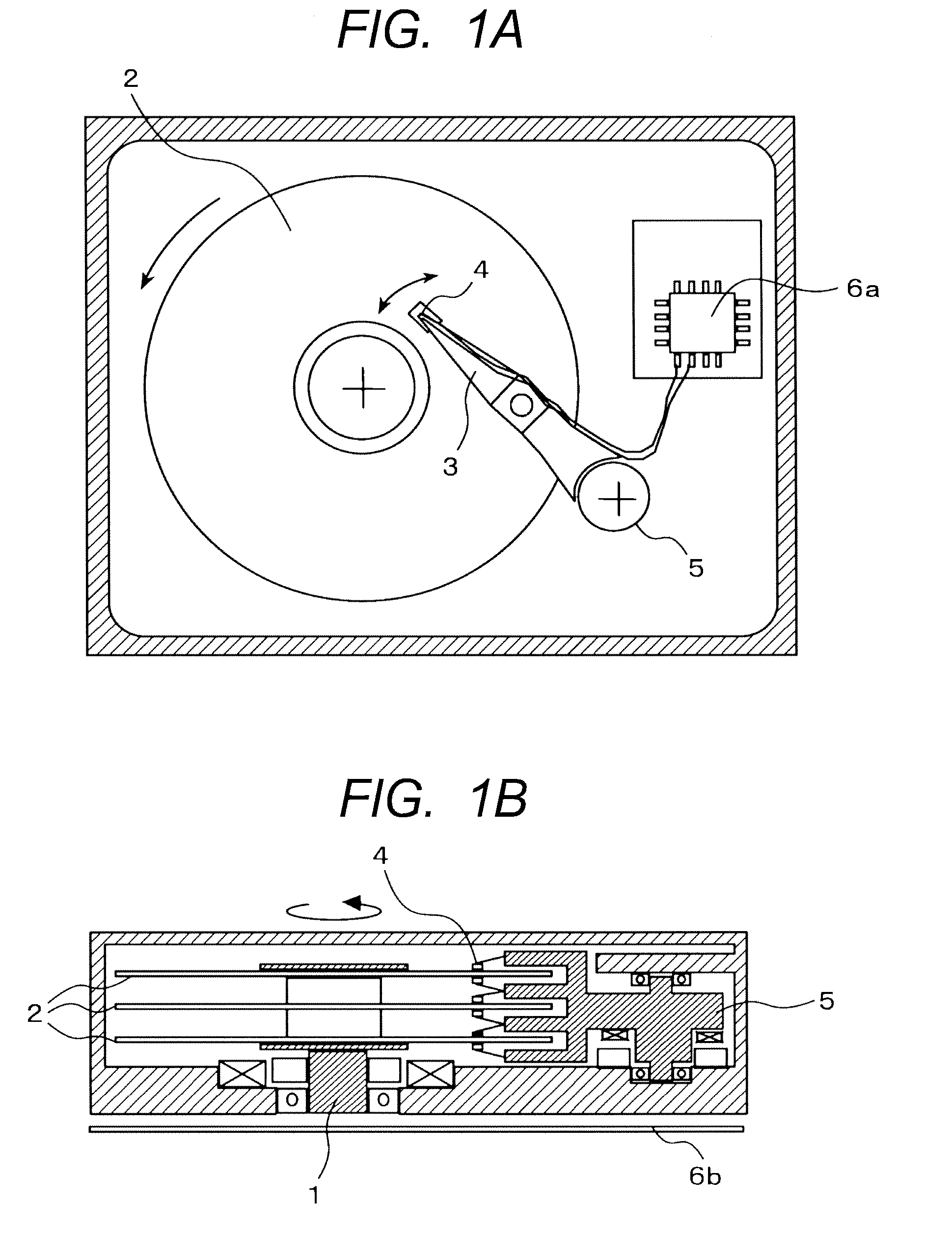
[0045]Preferred embodiments of the present invention will hereinafter be described with reference to the drawings. FIGS. 1A and 1B are a plan view and a cross-sectional view, respectively, illustrating a magnetic disk drive. The magnetic disk drive shifts a slider 4 secured to the tip of a suspension arm 3 to a targeted position on a magnetic disk (recording medium) to be rotated by a motor1. In addition, a magnetic head (perpendicular recording magnetic head and read head) mounted on the slider 4 reads and / or writes a magnetized signal. The shifting and positioning of the magnetic head is done by driving a rotary actuator 5 to selectively control the magnetic disk radial directional-position (track) of the magnetic head. A signal written to and read from the magnetic head is processed by a signal processing circuit 6a and a circuit 6b mounted on a substrate.

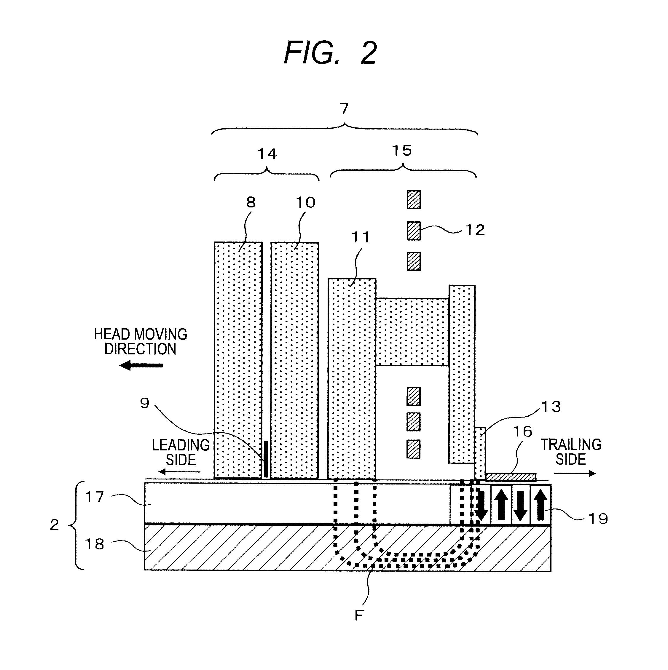
[0046]FIG. 2 illustrates the relationship between the configuration of a perpendicular recording magnetic head 7 and the magne...


PUM

PropertyMeasurementUnit
skew angleaaaaaaaaaa
taper angleaaaaaaaaaa
bevel angleaaaaaaaaaa

Abstract

The reduction in a recording magnetic field due to the narrowing of recording track width along with the improved surface recording density is prevented and the increasing of accuracy in the track width is achieved, enabling an improvement in recording performance. In a perpendicular magnetic recording head, a main pole 13 includes a first main pole portion 131 having an inverse trapezoidal shape with a bevel angle and a second main pole portion 132 laminated on the first main pole portion. The second main pole portion 132 has no bevel angle, is generally rectangular and defines track width. The second main pole portion has a tapered shape extending from the predetermined position of a flare portion toward an air bearing surface.

Description

CLAIM OF PRIORITY[0001]The present application claims priority from Japanese application serial No. 2010-57401, filed on Mar. 15, 2009, the content of which is hereby incorporated by reference into this application.BACKGROUND OF THE INVENTION[0002]1. Field of the Invention[0003]The present invention relates generally to a perpendicular recording magnetic head, a manufacturing method thereof and a magnetic disk drive using the magnetic head. In particular, the invention relates to narrowing of write track width by a perpendicular recording magnetic head and increasing of accuracy in the narrowed track width.[0004]2. Description of the Related Art[0005]An improvement in the surface recording density of a perpendicular recording magnetic head is required along with the recording density growth of magnetic disk drives. To meet the requirement, it is important to reduce write track width. However, the reduced write track width causes a reduction in the magnetic field generated from the t...

Claims


Application Information

Patent Timeline
Patent Type & Authority Applications(United States)
IPC IPC(8): G11B5/11H04R31/00
CPCG11B5/1278Y10T29/49052G11B5/3163G11B5/3116
Inventor ETOH, KIMITOSHIISHIBASHI, MASAYOSHIWATANABE, KATSUROHASHIMOTO, JUNICHI
Owner HITACHI LTD
Why Eureka
Try Eureka