Illuminating device and method for manufacturing thereof

a technology of illuminating devices and fa, applied in the direction of laminating printed circuit boards, light support devices, instruments, etc., can solve the problems of increasing cost, increasing cost, and not being suitable for a visual sensor illuminating device for fa, and achieve the effect of reducing cos

Active Publication Date: 2011-09-15
ORMON CORP
View PDF6 Cites 18 Cited by
  • Summary
  • Abstract
  • Description
  • Claims
  • Application Information

AI Technical Summary

Benefits of technology

[0032]A unit for changing the relative position of the second portion with respect to the first portion is further preferably arranged. According to the present invention, a plurality of types of illuminating devices having different specifications can be provided while reducing increase in cost.

Problems solved by technology

However, the illuminating devices of Japanese Unexamined Patent Publication Nos. 2002-184209 and 2002-83506 are not directed to image processing in the FA field in the first place.
Thus, the flexible substrate accommodate the number of product groups in order to achieve the large number of variations of the illumination field and the illumination distance in the illuminating device of Japanese Unexamined Patent Publication No. 2002-184209, which causes increase in cost.
The illuminating device of Japanese Unexamined Patent Publication No. 2002-83506 has a similar problem.
In the illuminating device disclosed in Japanese Unexamined Patent Publication No. 2008-139708, the lens must accommodate the variation of the field and the work distance, which causes increase in cost.
Furthermore, the lens may drop toward the workpiece since the lens is arranged on the side of the light irradiation surface with respect to the lens holder, and hence it is not suitable for a visual sensor illuminating device for FA.

Method used


Image

  • Illuminating device and method for manufacturing thereof
  • Illuminating device and method for manufacturing thereof
  • Illuminating device and method for manufacturing thereof

Examples


application example

F. Application Example

[0139]One example of the illuminating device manufactured by the manufacturing method described above will now be described.

[0140][f1. Direct Ring Shape]

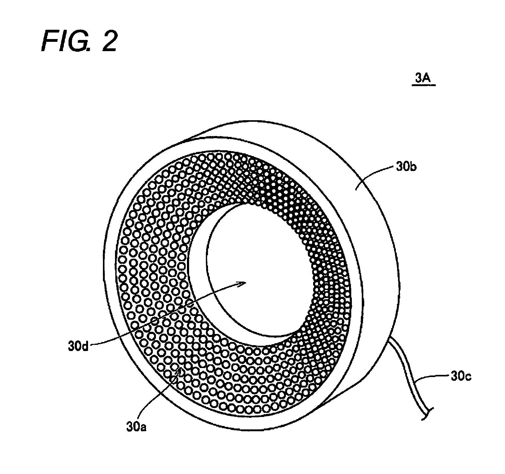
[0141]FIGS. 16A to 16C are views describing the direct ring type illuminating device manufactured using the manufacturing method according to the present embodiment. That is, FIGS. 16A to 16C show one example of a process used in manufacturing a direct ring type illuminating device 3A as shown in FIG. 2.

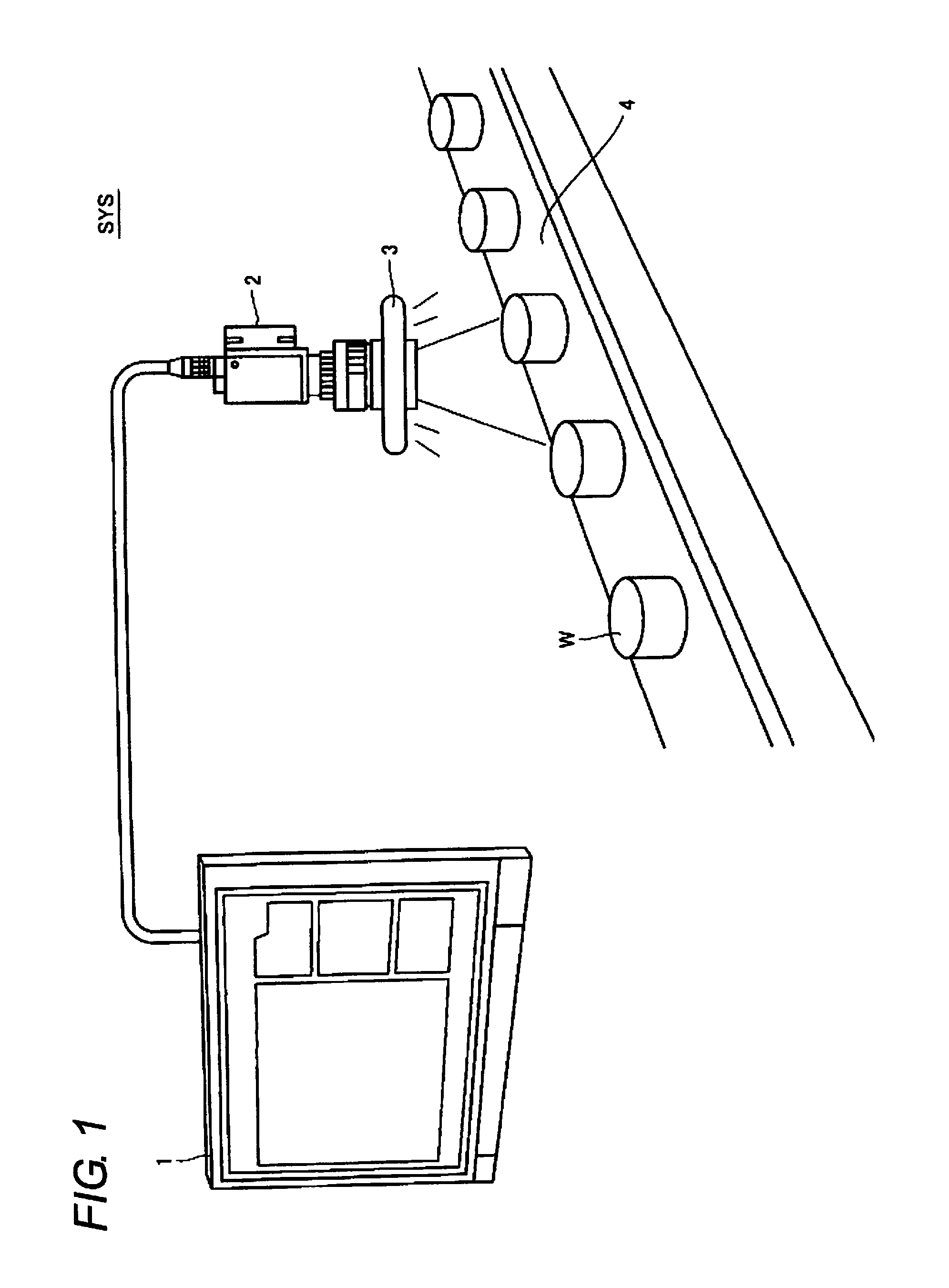
[0142]A large number of variations (product groups) for the illumination field and the illumination distance need to be accommodated for the direct ring type illuminating device as shown in FIG. 2 according to the field range etc. of the camera 2 to be coupled. According to the manufacturing method of the present embodiment, the size of the substrate piece to use for the illuminating device, that is, the number of units 14 to be arranged in one substrate piece can be arbitrarily set, and the shape of the common ...


PUM

PropertyMeasurementUnit
resistanceaaaaaaaaaa
widthaaaaaaaaaa
thicknessaaaaaaaaaa

Abstract

To provide a method for manufacturing a plurality of types of illuminating devices having different specifications while reducing cost. A substrate includes a common flexible portion and a plurality of units bendable with respect to the common portion, where the common portion includes a pad that is extended in the horizontal direction in the plane of the drawing and that is arranged for every predefined interval. In the present manufacturing method, a substrate piece is created by cutting the substrate mounted with the light emitting element in a first direction, the common portion in the substrate piece is formed according to the illuminating device to be manufactured, the relative position of the individual portion with respect to the formed common portion is respectively positioned, and the wiring for supplying power to the pad in the substrate piece is formed.

Description

CROSS REFERENCE TO RELATED APPLICATIONS[0001]This application claims priority based on 35 USC 119 from prior Japanese Patent Application No. 2010-055402 filed on Mar. 12, 2010, and Japanese Patent Application No. 2011-020892 filed on Feb. 2, 2011, entitled “ILLUMINATING DEVICE” and the entire contents of which are incorporated herein by reference.BACKGROUND OF THE INVENTION[0002]1. Technical Field[0003]The present invention relates to an illuminating device including a light emitting element, a method of manufacturing the same, and an illuminating device. In particular, the present invention relates to a ring-shaped illuminating device for illuminating an object to be imaged when acquiring an image.[0004]2. Related Art[0005]In the field of FA (Factory Automation) and the like, various types of image processing techniques are being used. Typically, an image processing technique for recognizing characters printed on an object to be examined, and examining for the presence of scratches...

Claims


Application Information

Patent Timeline
Patent Type & Authority Applications(United States)
IPC IPC(8): F21S4/00F21V21/00H05K13/00
CPCG01N21/8806Y10T29/49002F21K9/90H05B33/0827F21Y2101/02F21Y2103/022F21Y2111/001G03B15/05H05K1/0278H05K1/028H05K1/0281H05K1/189H05K3/0052H05K3/0058G03B2215/0539G03B2215/0575H05K2201/09081H05K2201/10106H05K2203/0228H05K2203/302G03B2215/0567F21K9/30F21K9/20F21Y2103/33F21Y2107/00F21Y2115/10H05B45/46
Inventor OBA, HITOSHINISHIMORI, NAOKIMATSUI, AKIRAISHIKAWA, NOBUHARUYAMASHITA, YOSHIHIROSUGA, TAKAHIROSUGIYAMA, KOSUKE
Owner ORMON CORP
Why Eureka
Try Eureka