Moving image encoding and decoding system

Inactive Publication Date: 2011-09-15
NTT DOCOMO INC
View PDF11 Cites 24 Cited by
  • Summary
  • Abstract
  • Description
  • Claims
  • Application Information

AI Technical Summary

Benefits of technology

[0045]According to operation of the moving picture encoding and decoding system, a prediction signal suitable for a moving

Problems solved by technology

However, when a signal of a target block includes dynamic textures, the differential signal becomes large because a pixel of the target block is not similar to the pixel in the prediction signal at the same location as that of the target block due to changes in the pixe

Method used


Image

  • Moving image encoding and decoding system
  • Moving image encoding and decoding system
  • Moving image encoding and decoding system

Examples


first embodiment

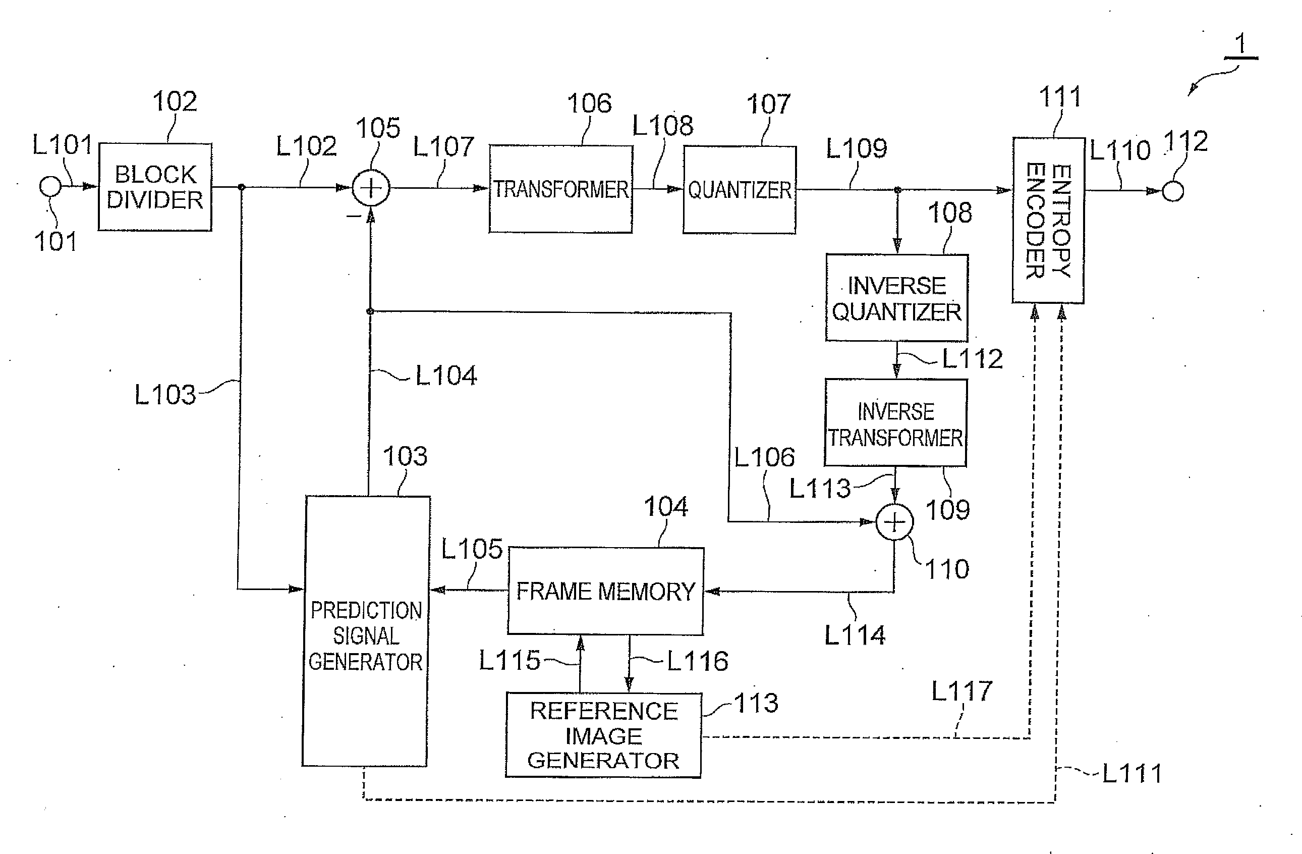
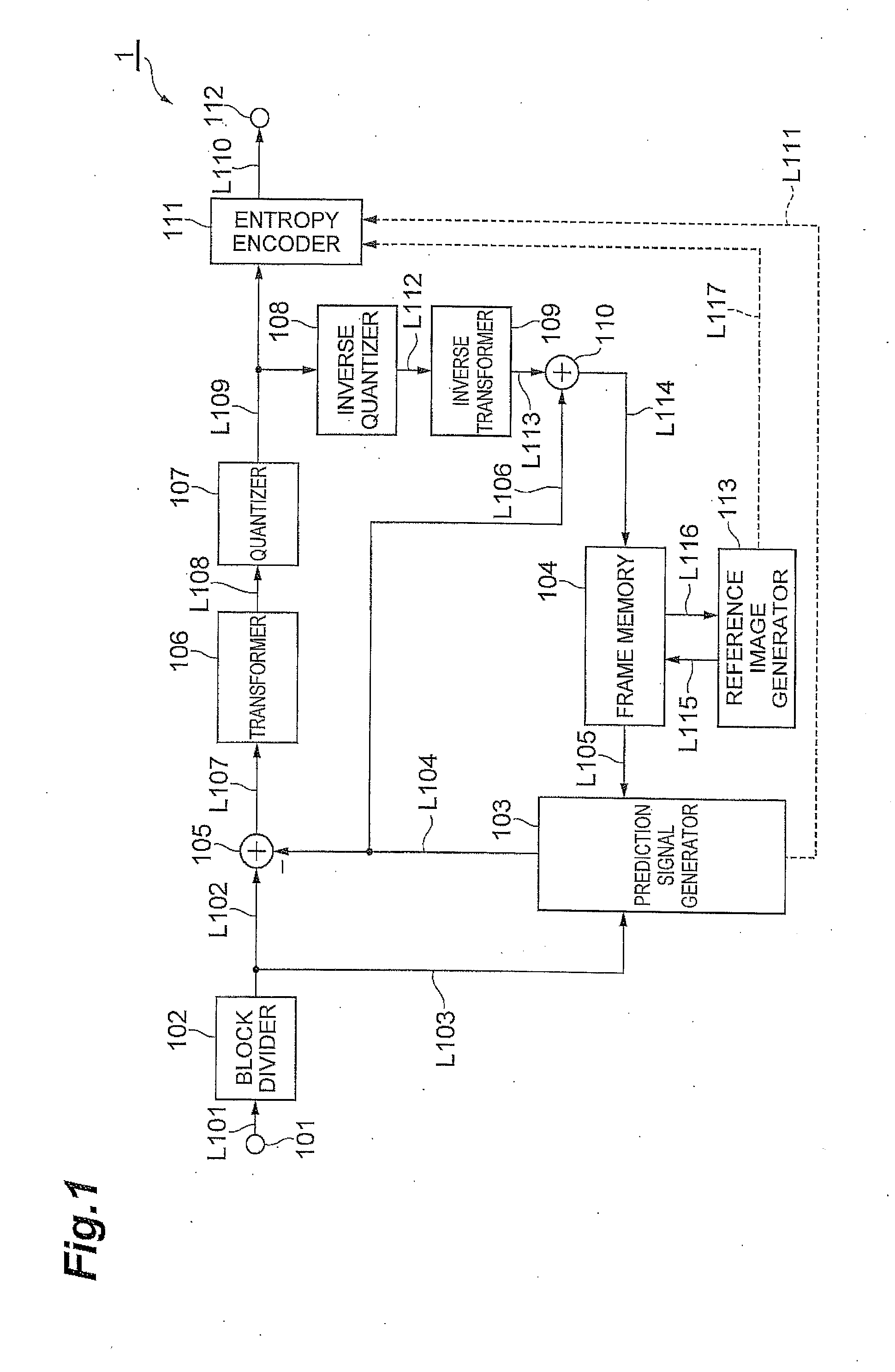
[0063](Moving picture encoding device) FIG. 1 is a block diagram showing a structure of an example moving picture encoder or encoding device included in the moving picture encoding and decoding system. The moving picture encoding device may be a computing device or computer, including for example software, hardware, or a combination of hardware and software, as described later, capable of performing the described functionality. The moving picture encoding device may be one or more separate systems or devices included in the moving picture encoding and decoding system, or may be combined with other systems or devices within the moving picture encoding and decoding system. In other examples, fewer or additional blocks may be used to illustrate the functionality of the moving picture encoding device. A moving picture encoder, or encoding device 1 shown in the diagram is provided with an input terminal (an input section) 101, a block divider 102, a prediction signal generator (a predict...

second embodiment

[0104]A second embodiment of the present invention is described with reference to the accompanying drawings. A moving picture encoding and decoding system that includes a moving picture encoding device and a moving picture decoding device according to the second embodiment partially differ from the moving picture encoding and decoding system that includes the moving picture encoding device and the moving, picture decoding device according to the first embodiment. The different points are mainly described below.

[0105](Moving picture encoding device) FIG. 9 is a block diagram showing an example structure of the moving picture encoding device according to the second embodiment of the present invention. A moving picture encoding device 50 shown in the diagram is provided with the input terminal (the input section) 101, the block divider (a dividing section) 102, the prediction signal generator (the prediction signal generation section) 103, the frame memory (the storage section) 104, th...


PUM


Abstract

A moving image encoding and decoding system reduces compressed moving picture data amounts by producing a prediction signal suitable for moving pictures including dynamic textures. The system includes a moving picture encoding device 1 that includes a block divider 102 receiving a target pixel signal, a prediction signal generator 103 producing a prediction signal, a subtractor 105 producing a differential signal, and a transformer 106 and quantizer 107 producing an encoded differential signal. The encoding device 1 also includes an inverse quantizer 108 and inverse transformer 109 producing a decoded differential signal, an adder 110 producing a reproduction signal, a frame memory 104 storing the reproduction signal as a reference image, and a reference image generator 113. The reference image generator 113 may obtain an observation matrix C by using a pre-existing reference image. The encoding system 1 produces a new reference image y″t+5 based on the observation matrix C and a state vector xt+5, and stores the new reference image in the frame memory 104. The prediction signal generator 103 produces the prediction signal by using at least the new reference image y″t+5.

Description

TECHNICAL FIELD[0001]The present invention relates to a moving picture encoding device, a moving picture decoding device, a moving picture encoding method, a moving picture decoding method, a moving picture encoding program, and a moving picture decoding program. Particularly, the invention relates to producing a prediction signal in prediction encoding and prediction decoding.BACKGROUND ART[0002]A compression encoding technology is used to efficiently transmit and store moving picture data. For example, as moving picture technology, MPEG-1, 2, 4, and H.261 to H.264 standards are widely used. In such moving picture encoding technology, a prediction signal of a target image serving as an encoding target is produced by using adjacent images side by side on a temporal axis and then a difference between the target image and the prediction signal is encoded, thereby realizing a data amount reduction. This technique is called inter-frame encoding.[0003]For example, in an encoding method s...

Claims


Application Information

Patent Timeline
IPC IPC(8): H04N7/26H04N19/50H04N19/147H04N19/423H04N19/46H04N19/503H04N19/51H04N19/577H04N19/61H04N19/625H04N19/70H04N19/91
CPCH04N19/51H04N19/573H04N19/593
Inventor SUZUKI, YOSHINORIBOON, CHOONG SENGOHM, JENS-RAINERWIEN, MATHIASSTOJANOVIC, ALEKSANDARTAN, THIOW KENG
Owner NTT DOCOMO INC
Why Eureka
Try Eureka