Noise reduction device

a technology of noise reduction and noise reduction, which is applied in the direction of active noise control, electrical transducers, instruments, etc., can solve the problems of noise in the seats becoming a problem, affecting comfort, and thus posing a serious problem in the quality of service, so as to achieve the effect of improving the quality of control

Active Publication Date: 2011-09-15
PANASONIC CORP
View PDF4 Cites 119 Cited by
  • Summary
  • Abstract
  • Description
  • Claims
  • Application Information

AI Technical Summary

Benefits of technology

[0016]It becomes possible by virtue of the above structure to detect the noise and execute control of noise reduction including such cases that obstacles exist. Thus provided is the noise reduction device capable of executing even steadier and higher quality of control under the environment where the obstacles exist.

Problems solved by technology

When providing information such as voice guidance and the like services to passengers sitting in seats inside an aircraft, a railcar and the like filled with loud noise, the noise in the seats becomes a problem.
Depending on a level of the noise, it can become a factor of physical and mental stresses to the passengers, and it therefore impairs the comfort.
The noise thus poses a serious problem in the quality of service especially when the service is provided for the passengers inside a cabin in an aircraft and the like.
The fuel consumption increases with increase in weight, and the cruising range decreases.
It hence causes a decline in economical efficiency and deterioration of the function as an aircraft.
The above method may make the noise-detecting microphone and the error microphone unable to continue their normal detecting functions if there is any obstacle such as a pillow, blanket, book and the like object placed around the microphones, thereby leaving a problem of presenting a possibility of increasing the noise in the control point depending on a condition of such obstacle.
According to the above conventional arts, however, the devices are designed to calculate the filter coefficient continuously in real time, and hence there has remained a possibility depending on the condition of the obstacle that the noise becomes larger than that without carrying out the control for noise reduction, and it discomforts the passengers when a control sound updated according to the calculated filter coefficient is output immediately.
Moreover, the above arts have not given any consideration to operation with the noise-detecting microphone covered with an obstacle, thereby making it unlikely to achieve a steady effect of the noise reduction.

Method used


Image

  • Noise reduction device
  • Noise reduction device
  • Noise reduction device

Examples


Embodiment Construction

[0031]Description is provided first of the fundamental concept of the present invention with reference to FIGS. 1A, 1B, 1C and 2, before detailing an exemplary embodiment of the invention.

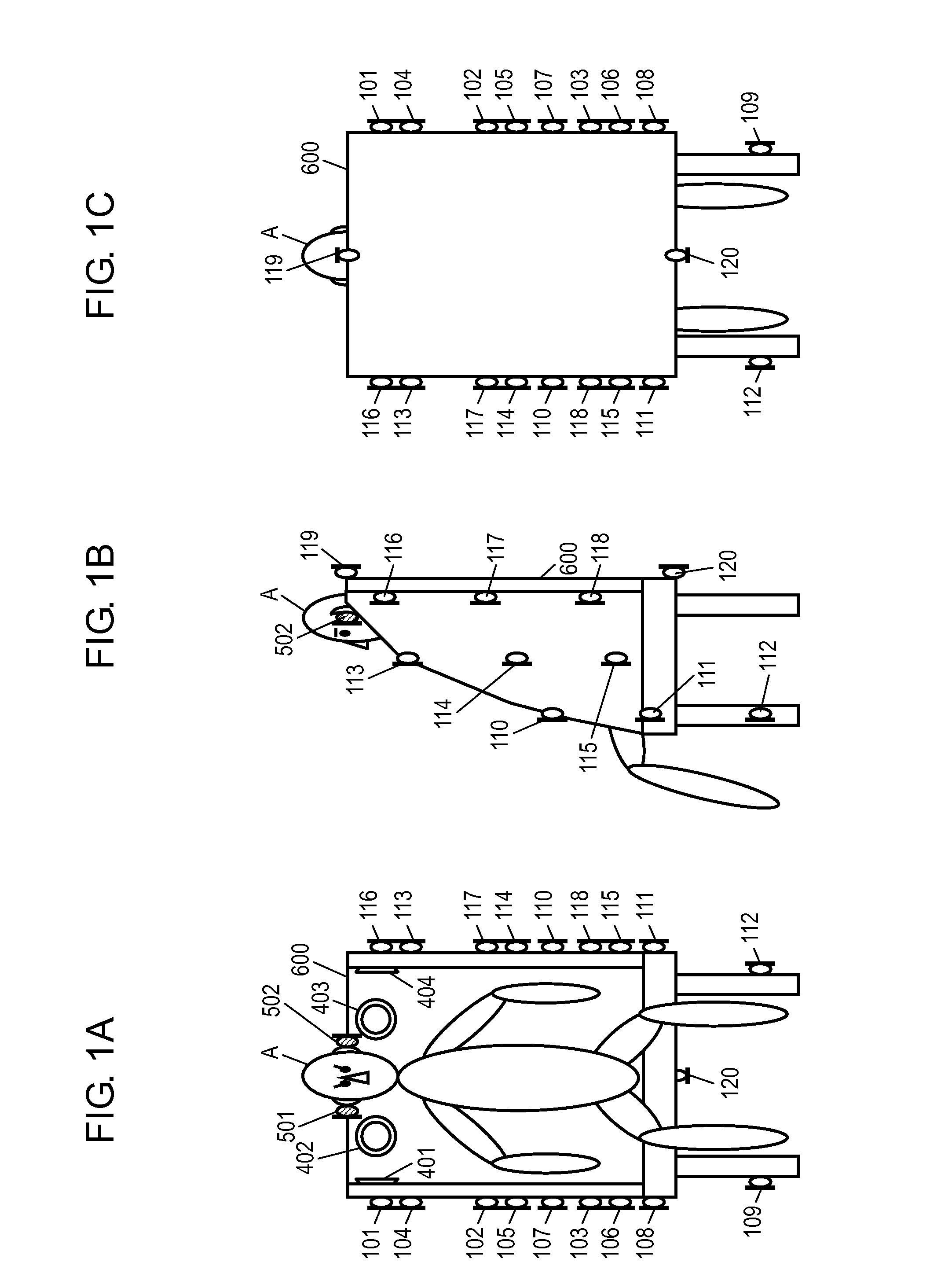
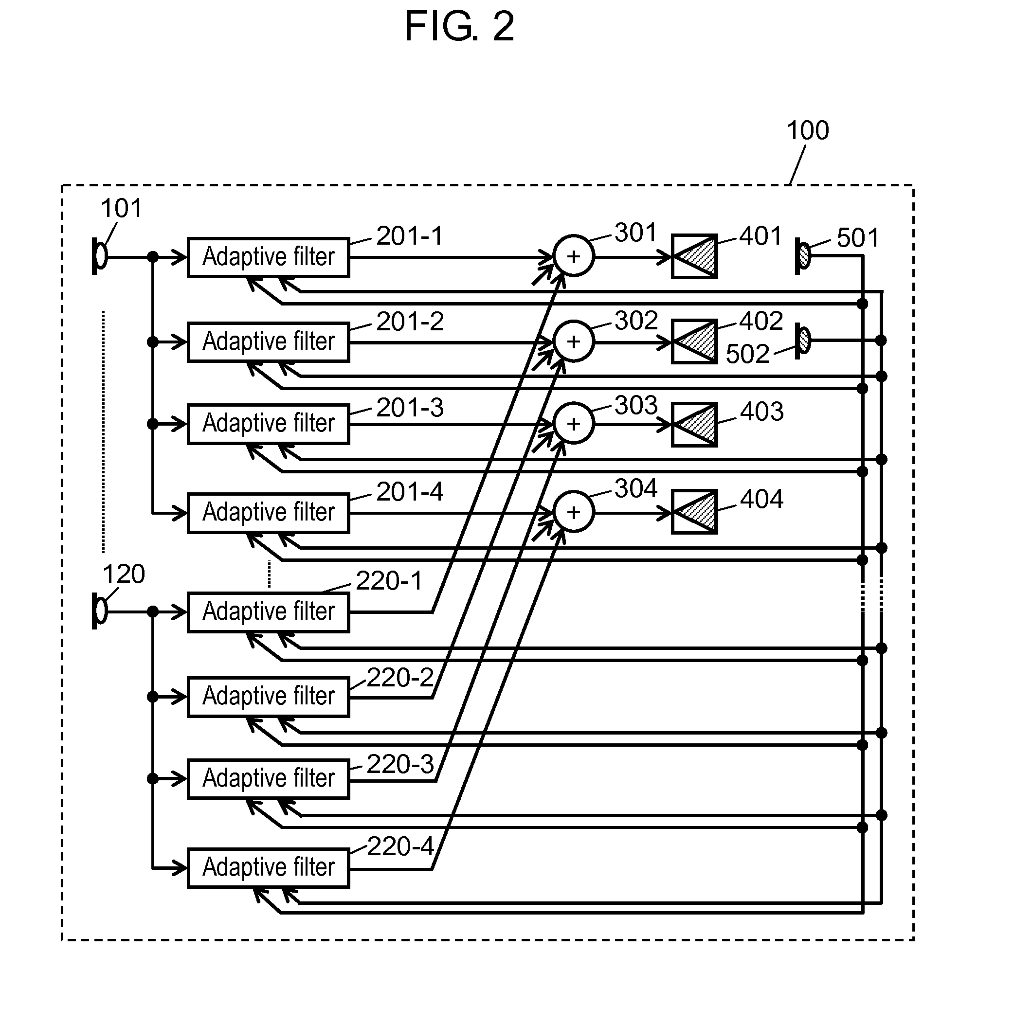
[0032]FIG. 1A is a front view showing an example of seat 600 of an aircraft with passenger (i.e., a user) A sitting therein, and FIGS. 1B and 1C are a side view and rear view respectively. FIG. 2 is a block diagram showing a circuit structure of a noise reduction device mounted to seat 600 shown in FIGS. 1A to 1C.

[0033]As illustrated in FIGS. 1A to 1C, noise-detecting microphones 101 to 120 are disposed to exterior sides of seat 600. Control speakers 401 to 404 are disposed to inner surfaces of seat 600 at positions of equal height to the ears of user A. Control points are set to be at the ears of user A, and error microphones 501 and 502 are placed on the ears of user A designated as the control points, as one example.

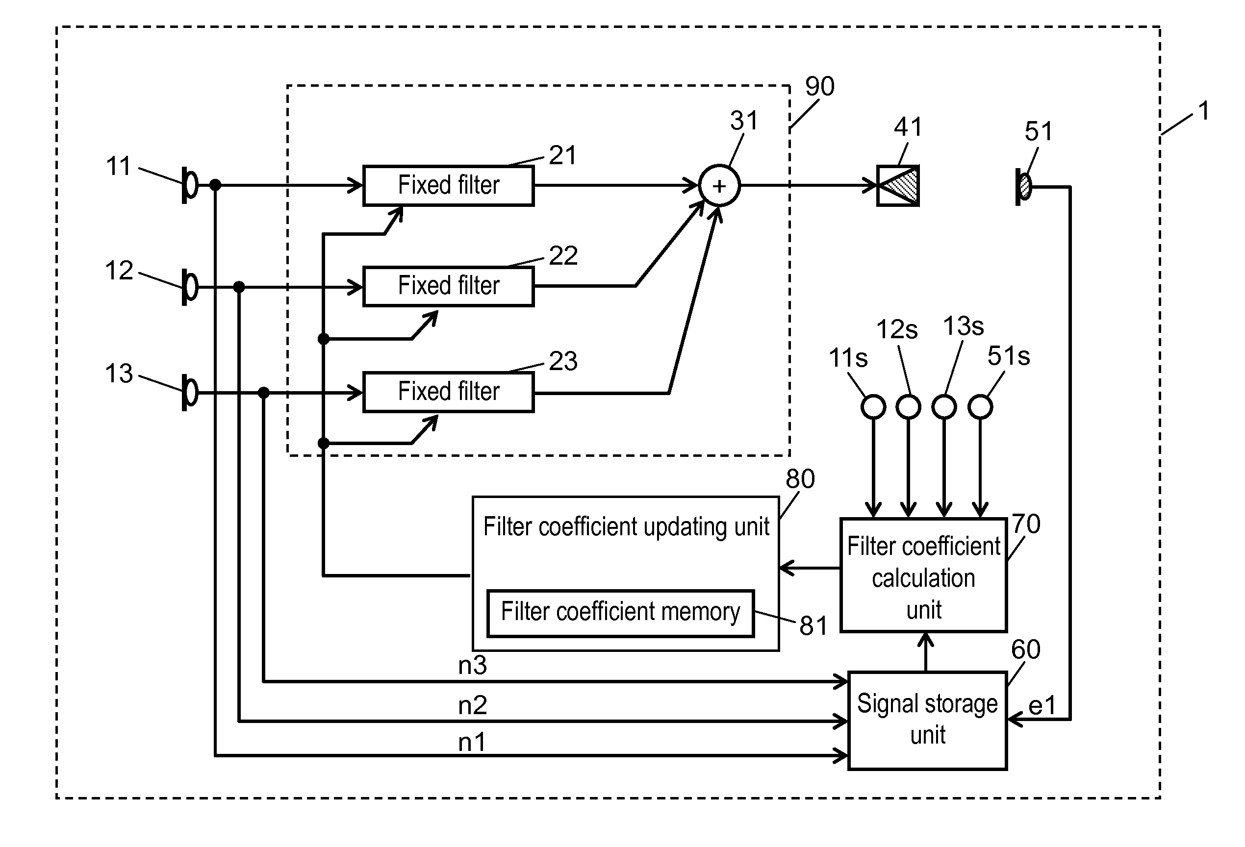
[0034]Noise reduction device 100 comprises noise-detecting microphones 101 to 12...


PUM


Abstract

A noise reduction device of the present invention comprises a control filter unit for generating a control sound signal to cancel out a noise, a control speaker for outputting a control sound according to the control sound signal from the control filter unit, an error microphone for detecting a residual sound by superimposing the noise upon the control sound output from the control speaker, and an obstacle detector for detecting an obstacle around the error microphone, wherein the control filter unit generates the control sound signal according to data from the error microphone and the obstacle detector.

Description

TECHNICAL FIELD[0001]The present invention relates to a noise reduction device and, in particular, it relates to a noise reduction device capable of actively reducing noise coming to a control point.BACKGROUND ART[0002]When providing information such as voice guidance and the like services to passengers sitting in seats inside an aircraft, a railcar and the like filled with loud noise, the noise in the seats becomes a problem.[0003]An interior space confined within a continuous wall like that of an aircraft or a car has a kind of sealed structure, and the noise environment remains persistent for the passengers when there is a noise source either inside or outside the space. Depending on a level of the noise, it can become a factor of physical and mental stresses to the passengers, and it therefore impairs the comfort. The noise thus poses a serious problem in the quality of service especially when the service is provided for the passengers inside a cabin in an aircraft and the like....

Claims


Application Information

Patent Timeline
Patent Type & Authority Applications(United States)
IPC IPC(8): G10K11/16
CPCG10K11/1784G10K11/1786G10K2210/503G10K2210/3025G10K2210/3221G10K2210/1281G10K11/17821G10K11/17825G10K11/17833G10K11/17854G10K11/17857G10K11/17881
Inventor ASAO, YOSHIFUMIMAEDA, TSUYOSHI
Owner PANASONIC CORP
Why Eureka
Try Eureka