Reduced Monobloc Multistage Drum of Axial Compressor

a compressor and monobloc technology, applied in the direction of wind motors, liquid fuel engines, wind motors with parallel air flow, etc., can solve the problems of significant mass, unfavourable hole bore holes in the wall section, and significant weight of reinforcements

Active Publication Date: 2011-09-15
TECHSPACE AERO
View PDF9 Cites 11 Cited by
  • Summary
  • Abstract
  • Description
  • Claims
  • Application Information

AI Technical Summary

Benefits of technology

[0019]This construction makes it possible to obtain a stiffened and reduced drum. Indeed, the fact of raising the support zone of the vanes creates a locking shoulder or half-box on the level of the wall under the vane row, i.e., exactly where the stresses are the greatest. Moreover, the fact of providing a continuous surface on the level of the central part delimiting the fluid stream avoids weakening the locking shoulder thus created. In comparison with the state of the art, this construction replaces the traditional fasteners like broachings and cells, as well as massive “leeks,” by a particular form of the wall on the level of the area intended to support the vanes. The interior surface of the locking shoulder or half-box is preferably free of rib, for example of the “leek” type being used only as reinforcement and adding massiveness. The vanes can be integrally formed with the rotor or even be welded onto the surface in question. Alternatively, a bottom part of the vanes can be integrally formed with the rotor, the remaining part of the vanes being then welded at this part.
[0021]According to one advantageous mode of the present application, the exterior surface of the central part of the annular area is generally smooth, preferably generally cylindrical, conical or of bulging form over the length of the aforesaid surface according to the axis of rotation.
[0022]A similar construction of the exterior surface of the central part has the advantage of guaranteeing a good aerodynamics.

Problems solved by technology

These reinforcements appreciably weigh down the drum because of their massiveness.
The construction proposed in this document is interesting from a point of view of stiffness but imposes, however, a significant massiveness which is penalizing notably for the weight of the compressor in itself.
These holes bored in the wall section are unfavourable, because they partially weaken it.

Method used


Image

  • Reduced Monobloc Multistage Drum of Axial Compressor
  • Reduced Monobloc Multistage Drum of Axial Compressor
  • Reduced Monobloc Multistage Drum of Axial Compressor

Examples


Embodiment Construction

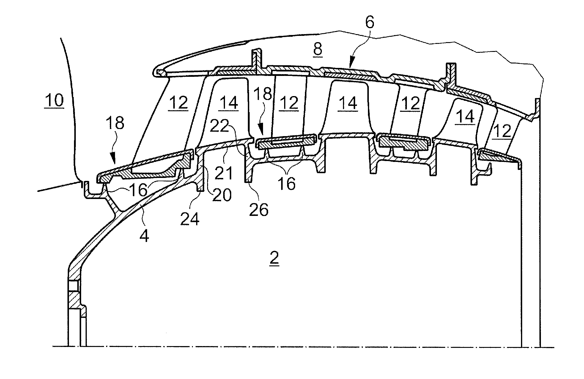
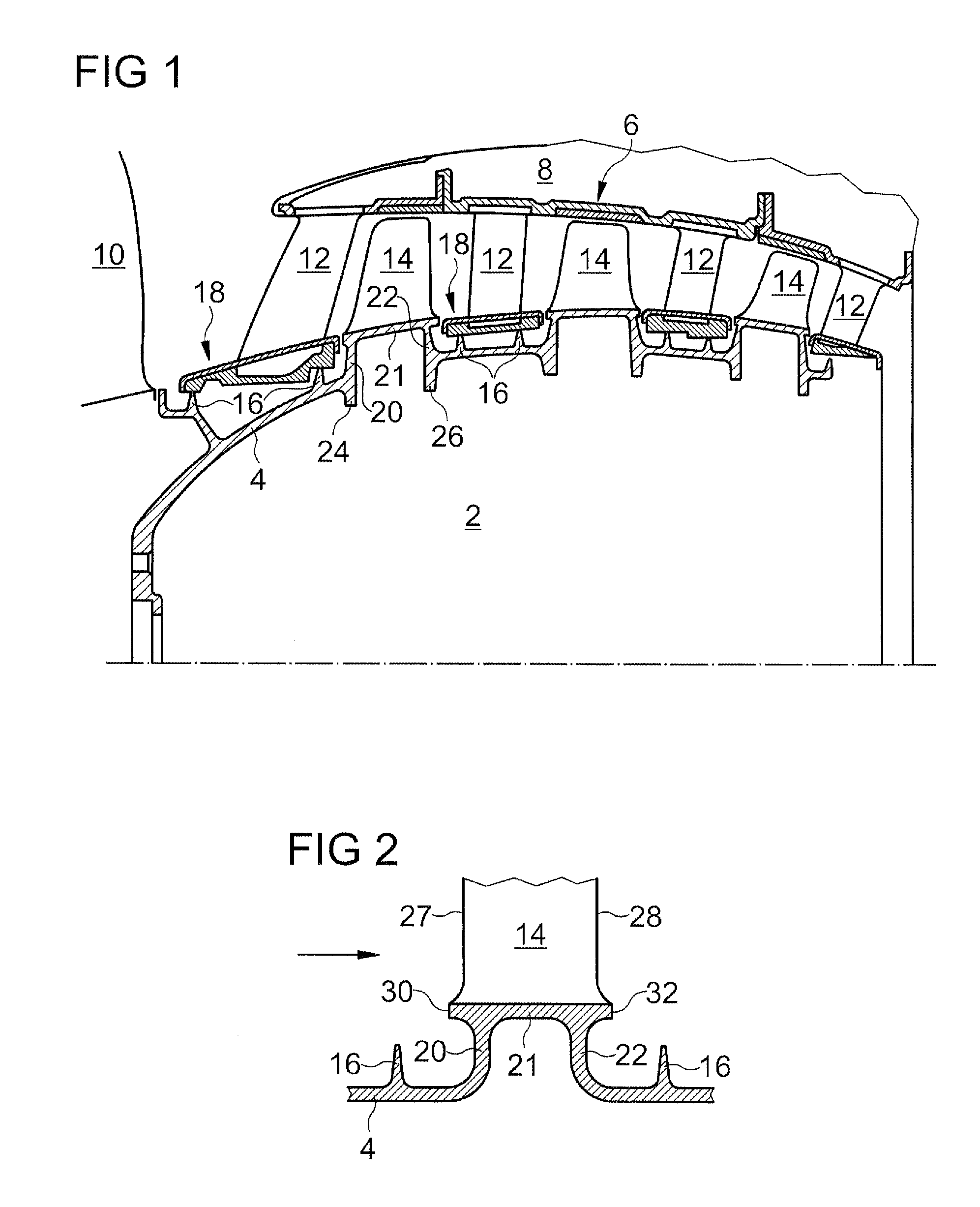
[0017]The present application aims to propose a drum rotor stage or a drum alleviating at least one of the above-mentioned known disadvantages, more particularly the present application aims to propose a reduced drum.

[0018]The present application discloses an axial turbomachine compressor drum rotor stage, the aforesaid compressor being intended to be crossed by a fluid stream in a direction generally oriented according to the axis of rotation, the rotor stage comprising a generally symmetrical wall in revolution in relation to the axis of rotation and forming a hollow body, the aforesaid wall comprising a veil and an annular area intended to support a row of vanes and integrally formed with the veil; each of the aforesaid vanes having a leading edge and a trailing edge; remarkable in that the aforesaid annular area comprises a central part raised in relation to the aforesaid veil, whose exterior surface delimits the fluid stream between the vanes, is all in one block, and is integr...


PUM


Abstract

A rotor stage of an axial turbomachine compressor drum includes a symmetrical wall in rotation around the axis of rotation. The wall comprises a veil defining the general form of the drum and an annular area intended to support a row of vanes, the aforesaid area being integrally formed with the veil. This area has a particular form in that it has an exterior surface delimiting the fluid stream, which is elevated in relation to the veil. This area has a “U”-shape cross-section, of which the open part is directed towards the axis of rotation. The annular area comprises two wall parts, one upstream and one downstream, ensuring the connection with the veil and being used as stiffeners. They are preferably perpendicular to the axis of rotation or inclined in relation to the perpendicular. The junction of each upstream and downstream wall part with the central part of the support area is at the distance of the corresponding edge of the central part, so as to avoid certain stress concentrations.

Description

[0001]This application claims priority under 35 U.S.C. §119 to European Patent Application No. 10156427, filed 12 Mar. 2010, which is incorporated herein by reference for all purposes.BACKGROUND[0002]1. Field of the Application[0003]The present application relates to an axial turbomachine compressor drum, more particularly with a rotor stage of such a compressor, knowing that the drum can be composed of an assembly of several parts corresponding to different rotor stages; and more particularly still, with construction measurements of an axial turbomachine compressor drum, these measurements being intended in particular to reduce the drum.[0004]2. Description of Related Art[0005]In general, a compressor drum is a generally symmetrical hollow body in revolution in relation to its axis of rotation, which corresponds to the axis of the turbomachine. The hollow body has a general oval or ogive shape according to the form of the flow. Several rows of vanes are fixed on the drum so as to f...

Claims


Application Information

Patent Timeline
Patent Type & Authority Applications(United States)
IPC IPC(8): F04D29/54
CPCF01D5/063F01D5/3061F04D29/329F04D29/053F04D29/321F01D5/34
Inventor WLASOWSKI, MICHEL
Owner TECHSPACE AERO
Why Eureka
Try Eureka