
Battery state estimator using multiple sampling rates

a battery state and estimation method technology, applied in the field of estimating battery parameters, can solve the problems of limited computational power, inability to guarantee the accuracy of all battery parameters in a complex model with as many frequency modes as possible, and is neither practical nor necessary to cover all frequency modes in one model

Active Publication Date: 2011-09-15
GM GLOBAL TECH OPERATIONS LLC
View PDF3 Cites 46 Cited by
  • Summary
  • Abstract
  • Description
  • Claims
  • Application Information

AI Technical Summary

Benefits of technology

[0010]In accordance with the teachings of the present invention, a method is disclosed for estimating vehicle battery parameters that uses two different sampling rates. The method samples a battery terminal voltage and current at a high sampling rate to estimate the battery open circuit voltage and high frequency resistance. The battery stat...

Problems solved by technology

The reason for this is mainly due to limited computational power and memory available for onboard applications.
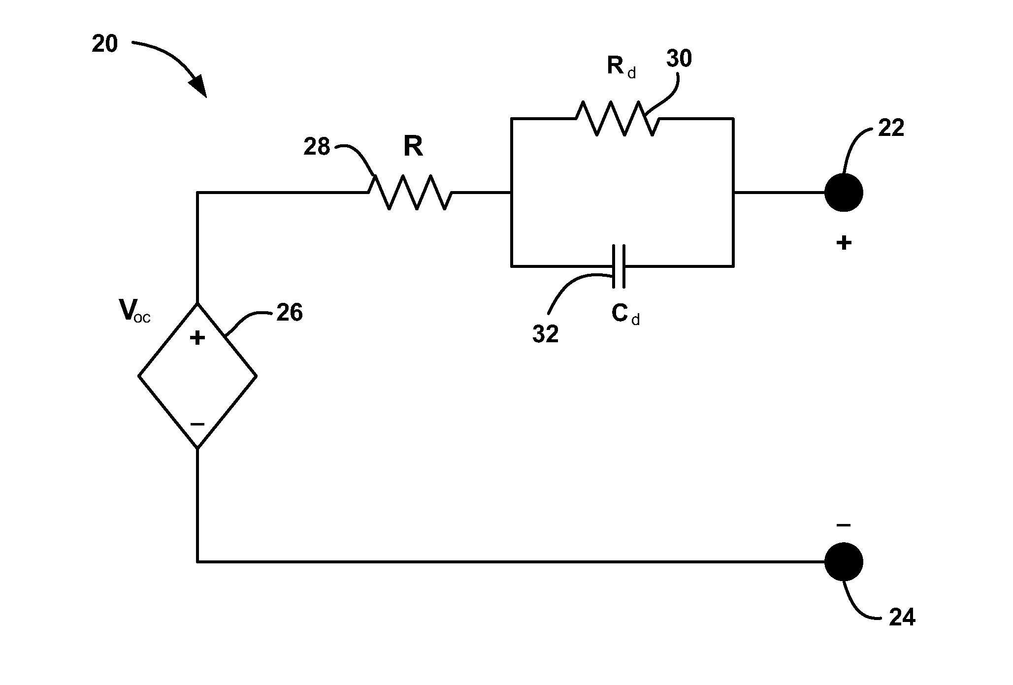
In fact, even if there were unlimited computational power and memory, the accurate estimation of all battery parameters in a complex model with as many frequency modes as possible cannot be guaranteed because the excitation of signals, normally battery terminal voltage and terminal current, is limited.
Therefore, it is neither practical nor necessary to cover all frequency modes in one model as long as the estimation error caused by model uncertainties is within an acceptable range for a specific application.
A simple model with limited frequency modes inevitably introduces errors and uncertainties because it cannot fully cover all feature frequencies for various applications.
Without adding more dynamic components, i.e., additional frequency modes, into the battery model, these algorithms have difficulties capturing both fast dynamics for SOC estimation and slow dynamics for power prediction.
Therefore, the accuracy and robustness of the algorithms are compromised for multiple applications.
In other words, the sampling rate that measures the battery terminal voltage and current is generally too fast to accurately determine the parameters generated from the RC pair, which results in a somewhat inaccurate representation of the battery's power capabilities at any given point in time.

Method used


Image

  • Battery state estimator using multiple sampling rates
  • Battery state estimator using multiple sampling rates
  • Battery state estimator using multiple sampling rates

Examples


Embodiment Construction

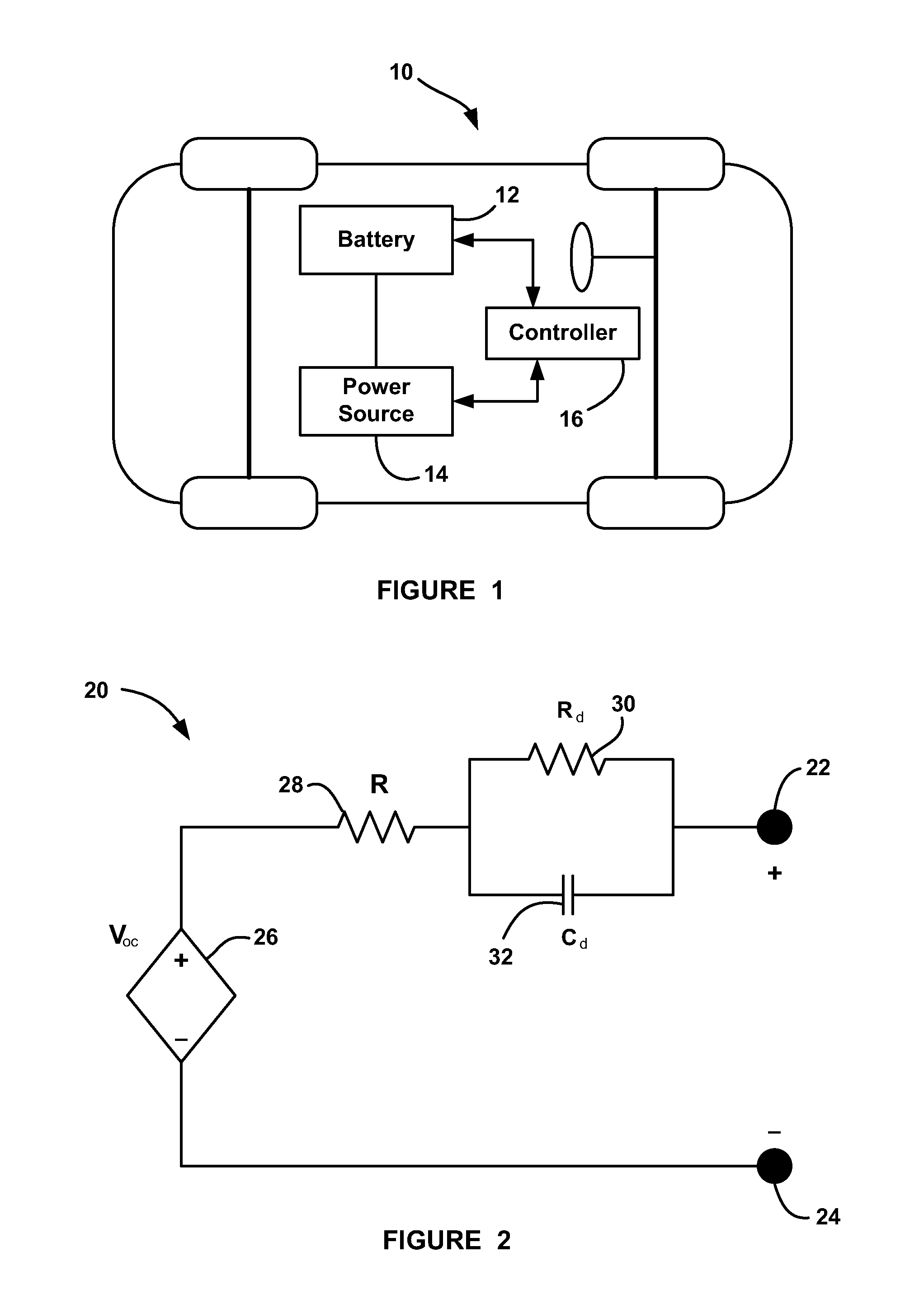
[0015]The following discussion of the embodiments of the invention directed to a method for estimating battery parameter using two different sampling rates is merely exemplary in nature, and is in no way intended to limit the invention or its applications or uses. For example, the invention has particular application for an on-board algorithm for in-vehicle applications. However, as will be appreciated by those skilled in the art, the battery state estimator of the invention will have other applications other than vehicle applications.

[0016]The present invention proposes a new battery state estimator that uses multiple sampling rates and a simple battery model with limited frequency modes, but which emphasizes different feature frequencies for different applications. This battery state estimation method significantly improves the robustness and accuracy for SOC estimation and power prediction, without introducing a significant amount of additional computation and memory usage.

[0017]...


PUM


Abstract

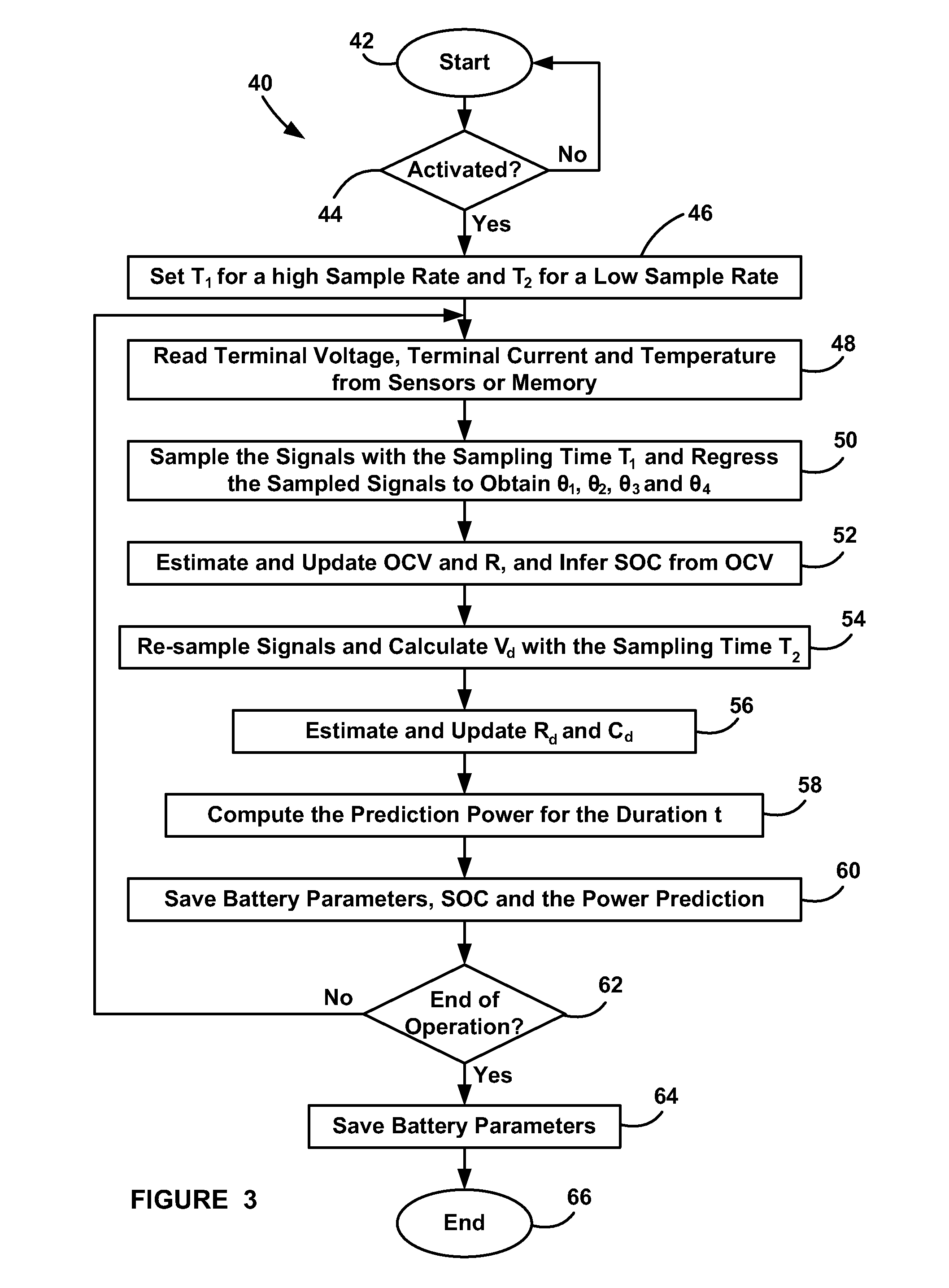
A method for estimating vehicle battery parameters that uses two different sampling rates. The method samples a battery terminal voltage and current at a high sampling rate to estimate the battery open circuit voltage and high frequency resistance. The battery state of charge (SOC) is derived from the open circuit voltage. Next, the battery terminal voltage and current are re-sampled at a low sampling rate. Other battery parameters can be extracted from the low-rate sampled signals. Next, all of the battery parameters that were obtained from the two sampling rates are used together to predict battery power.

Description

BACKGROUND OF THE INVENTION[0001]1. Field of the Invention[0002]This invention relates generally to a method for estimating battery parameters that uses multiple sampling rates and, more particularly, a method for estimating battery parameters that uses two different sampling times where a battery terminal voltage and current are sampled at a high sampling rate to estimate the battery open circuit voltage (OCV) and high frequency resistance and the battery terminal voltage and current is re-sampled at a low sampling rate to estimate battery parameters that can be used to estimate battery power.[0003]2. Discussion of the Related Art[0004]Electric vehicles are becoming more and more prevalent. These vehicles include hybrid vehicles, such as the extended range electric vehicles (EREV) that combines a battery and a main power source, such as an internal combustion engine, fuel cell systems, etc., and electric only vehicles, such as the battery electric vehicles (BEV). All of these types...

Claims


Application Information

Patent Timeline
IPC IPC(8): G01R31/36G01N27/416
CPCG01R31/3662G01R31/3651G01R31/367G01R31/389
Inventor LIN, JIANTANG, XIDONGKOCH, BRIAN J.VERBRUGGE, MARK W.
Owner GM GLOBAL TECH OPERATIONS LLC
Learn More