Multiple damage method for structural design optimization

a structural design and optimization technology, applied in multi-objective optimisation, instruments, cad techniques, etc., can solve problems such as methods for optimizing structural design

Active Publication Date: 2011-09-15
AIRBUS OPERATIONS SL
View PDF5 Cites 19 Cited by
  • Summary
  • Abstract
  • Description
  • Claims
  • Application Information

AI Technical Summary

Benefits of technology

[0013]One object of the present invention is to provide a computer-aided method for optimizing the structural design of parts subjected to the possibility of suffering multiple damages having significant effects on its structural integrity.
[0014]Another object of the present invention is to provide a computer-aided method for optimizing the structural design of an aircraft fuselage section subjected to the possibility of suffering multiple damages having significant effects on its structural integrity.
[0015]Another object of the present invention is to provide a computer-aided method for optimizing the structural design of an aircraft fuselage section subjected to the possibility of suffering multiple damages having significant effects on its structural integrity caused by a PBR event and / or an UERF event and / or an ice shedding event.
[0024]In another preferred embodiment, one possible damaged fuselage section is a replica of the un-damaged fuselage section but eliminating, or degrading the properties of, those zones belonging to said skin, said frames and said stiffeners that will be directly involved in one of said events. Hereby it is achieved a multi-model method for optimizing the structural design of an aircraft fuselage section in which the damaged models are easily obtained.

Problems solved by technology

One of the problems raised by this aircraft configuration is related to failure events such as a PBR (“Propeller Blade Release”) i.e. an event where a blade of one of the propeller engines comes off and hits the fuselage, a UERF (“Uncontained Engine Rotor Failure”), i.e. an event where a part of the rotor of the engine brakes, it is released and hits the fuselage, an ice shedding event where ice shedding created in the tips of the blades can be thrown at high speed over the fuselage, or any other “Large Damage” event.
Although the aircraft industry demand constantly methods for optimizing the structural design of aircraft parts there are not known methods for optimizing the structural design of aircraft parts subjected to multiple damages caused by a PBR event, an UERF event, an ice shedding event or any other similar event.

Method used


Image

  • Multiple damage method for structural design optimization
  • Multiple damage method for structural design optimization
  • Multiple damage method for structural design optimization

Examples


Embodiment Construction

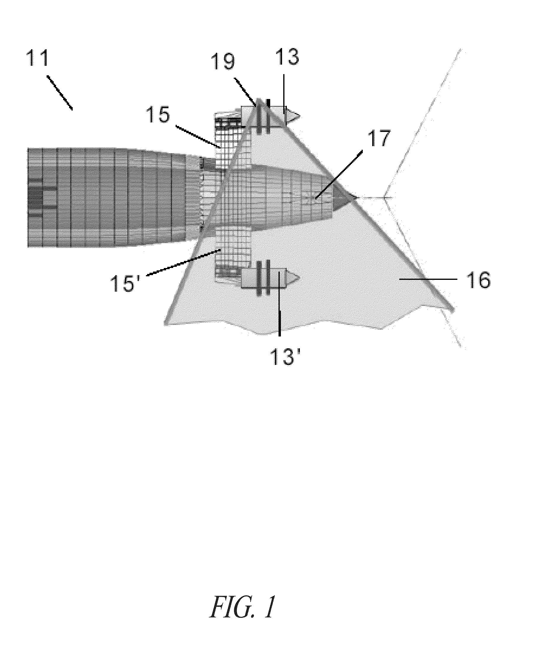
[0036]A preferred embodiment of this invention will be detailed described for optimizing the structural design of a fuselage section of an aircraft with an open-rotor engine such as the aircraft illustrated in FIG. 1 having in its rear part 11 open-rotor engines 13, 13′ supported by pylon arms 15, 15′. Although in this description only damages caused by a PBR event will be specifically mentioned, the skilled man will readily understood that the invention is applicable to any type of damages having significant effects on the structural integrity of the fuselage section.

[0037]The computer-aided optimizing method according to this invention refers to a design of the fuselage section 17 that assures its structural integrity in the event of the release of the propeller blade 19, or any other of the blades of said engines 13, 13′ that may impact the fuselage section 17 following any trajectory within the area 21 that includes all the possible trajectories being considered.
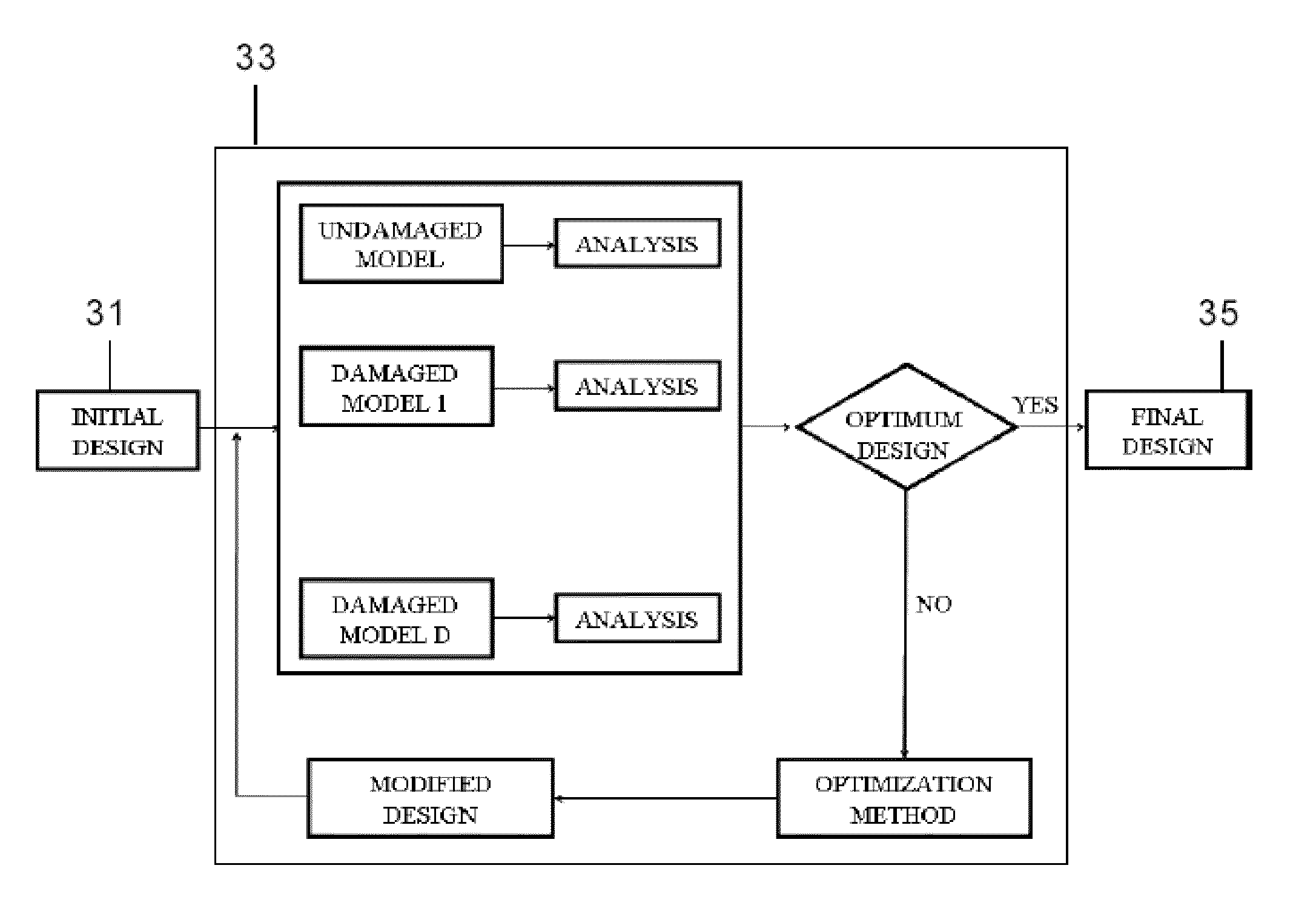
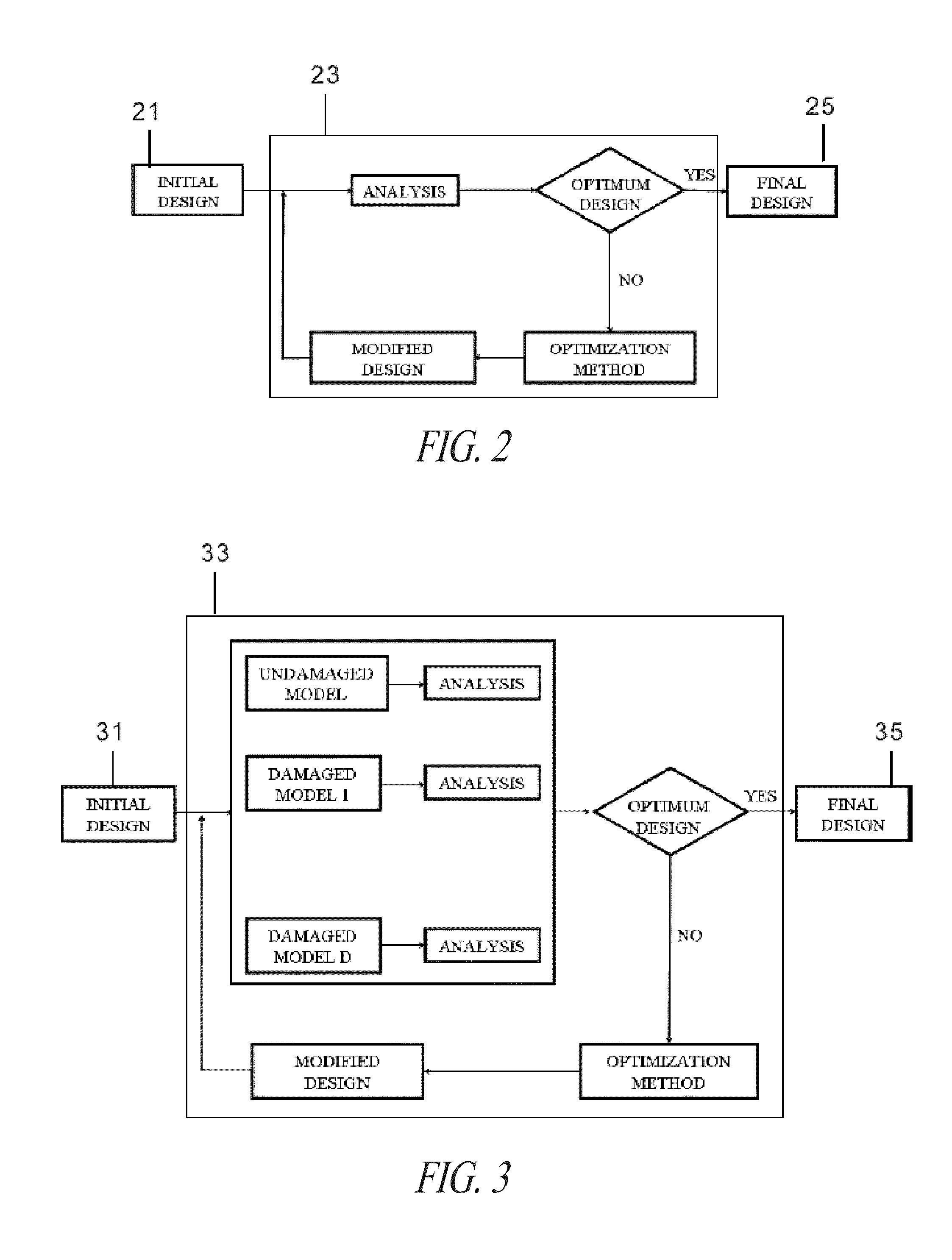
[0038]The approa...


PUM


Abstract

A computer-aided method for carrying out the structural design of a part subjected to damages having significant effects on its structural integrity, such as an aircraft fuselage section subjected to a PBR event, comprising steps of: Obtaining FE models that include all the relevant information for an optimization analysis for the un-damaged part and for at least one possible damaged part; Defining at least one design variable of said part and at least one design constraint and one load case for said un-damaged part and for said damaged part; Providing at least one simulation module for analyzing one or more failure modes of said part; Iteratively modifying the design variables of said part for the purpose of optimizing said target function by analyzing simultaneously said un-damaged part and said at least one damaged part using said at least one simulation module.

Description

CROSS-REFERENCE TO RELATED APPLICATION[0001]This application claims the benefit under 35 U.S.C. §119(e) of Spanish Patent Application No. ES 201030373, filed Mar. 15, 2010, which application is incorporated herein by reference in its entirety.FIELD OF THE INVENTION[0002]The present invention relates to a method for optimizing the structural design of parts subjected to the possibility of suffering damages having significant effects on its structural integrity and, more in particular, to a method for optimizing the structural design of aircraft fuselage sections subjected to the possibility of suffering said damages.BACKGROUND[0003]There are known commercial aircrafts (CBA vector 123, SARA, AVANTI, 7J7) powered with propeller engines located in the rear part of the aircraft supported by the fuselage by means of pylons.[0004]One of the problems raised by this aircraft configuration is related to failure events such as a PBR (“Propeller Blade Release”) i.e. an event where a blade of on...

Claims


Application Information

Patent Timeline
Patent Type & Authority Applications(United States)
IPC IPC(8): G06F17/50
CPCG06F17/5095G06F2217/46G06F2217/08G06F2217/06G06F30/15G06F2111/04G06F2111/06G06F2113/28G06F30/23Y02T90/00
Inventor MARASCO, ANDREA IVANGONZALEZ, ESTEBAN MARTINOSANTOLALLA, EDUARDO VINUEGARCIA, AITOR BALDOMIRGARCIA, JACOBO DIAZIBANEZ, SANTIAGO HERNANDEZ
Owner AIRBUS OPERATIONS SL
Why Eureka
Try Eureka