Fans-motor assembly for condenser laundry dryer machine and condenser laundry dryer machine comprising said assembly

a technology of condenser laundry dryer and condenser dryer, which is applied in the field of laundry dryers, can solve the problems of limited torque density of the motor, increasing the degree of humidity of the area, and the limited diameter of the rotor, so as to avoid the connection of the board, reduce the noise level of the electric motor, and facilitate the connection of the device.

Active Publication Date: 2011-09-22
ASKOLL HLDG SRL
View PDF19 Cites 4 Cited by
  • Summary
  • Abstract
  • Description
  • Claims
  • Application Information

AI Technical Summary

Benefits of technology

[0022]The use of a synchronous permanent magnet electric motor in place of the asynchronous motor universally used in the prior art allows the rotor which drives the drive shaft to be brought to the exterior, increasing the arm which separates the axis of rotation from the air gap and consequently obtaining greater torque density. In this way it is possible to limit considerably the production costs and the overall dimensions of the electric motor while observing the torque conditions necessary for ensuring the rotation of the rotating drum in normal load conditions.
[0031]The reels may comprise, at the their end turned towards the exterior of the radial pattern, flanges designed to attach ferromagnetic inserts which act as pole pieces of the magnetic circuit defined by the lamination pack. In this way said flanges can advantageously define a continuous annular belt wherein the ferromagnetic inserts are set. The continuity of said annular belt ensures a constant air gap between it and the permanent magnet of the rotor, contributing to the low noise levels of the electric motor.
[0032]Moreover the fans-motor assembly according to the present invention may comprise at least one control board of the electric motor integral with the internal stator. Said board can be mounted directly on the stator, even inside the same casing which encloses the active parts thereof. This embodiment allows the avoiding of the connection of the board to the motor by means of costly cablings which are difficult to install.
[0033]The control board may comprise connection means, made for example in the form of female electrical connectors, for power supply and / or signal cables. These connection means can be accessible from the exterior of the casing by means of apertures thereof, thus allowing a rapid connection of the device to the electrical circuit of the laundry dryer machine, for example via the simple insertion of the plugs of the cables inside the connectors.
[0034]The external rotor may comprise a container cup which embraces the external periphery of the internal stator. Said container cup can have a cylindrical internal surface whereto a metal ring, also cylindrical, is coupled, which in turn supports an annular permanent magnet. This configuration allows the container cup in plastic material to be produced via a normal moulding operation.

Problems solved by technology

Laundry washing machines of this type have however a limited thermal efficiency and also contribute to raising the degree of humidity of the area in which they are installed.
More particularly, the limited diameter of the rotor produces a motor with relatively low torque density.
The dimensions of the electric motor mean above all a high cost, due to the need to use a high quantity of active materials.
Moreover, the overall dimensions of the motor determine constructional compromises which reduce the overall efficiency of the laundry dryer machine.
Given however the considerable weight of the stator casing, the bushings whereon it is mounted tend to wear rapidly, requiring inconvenient operations of maintenance.
It should be noted also that, again due to the overall dimensions of the motor, it cannot be directly associated with a control board, which should be installed in another position of the machine and then connected to the motor itself by means of costly cablings, which can moreover be damaged causing breakdowns.

Method used


Image

  • Fans-motor assembly for condenser laundry dryer machine and condenser laundry dryer machine comprising said assembly
  • Fans-motor assembly for condenser laundry dryer machine and condenser laundry dryer machine comprising said assembly
  • Fans-motor assembly for condenser laundry dryer machine and condenser laundry dryer machine comprising said assembly

Examples


Embodiment Construction

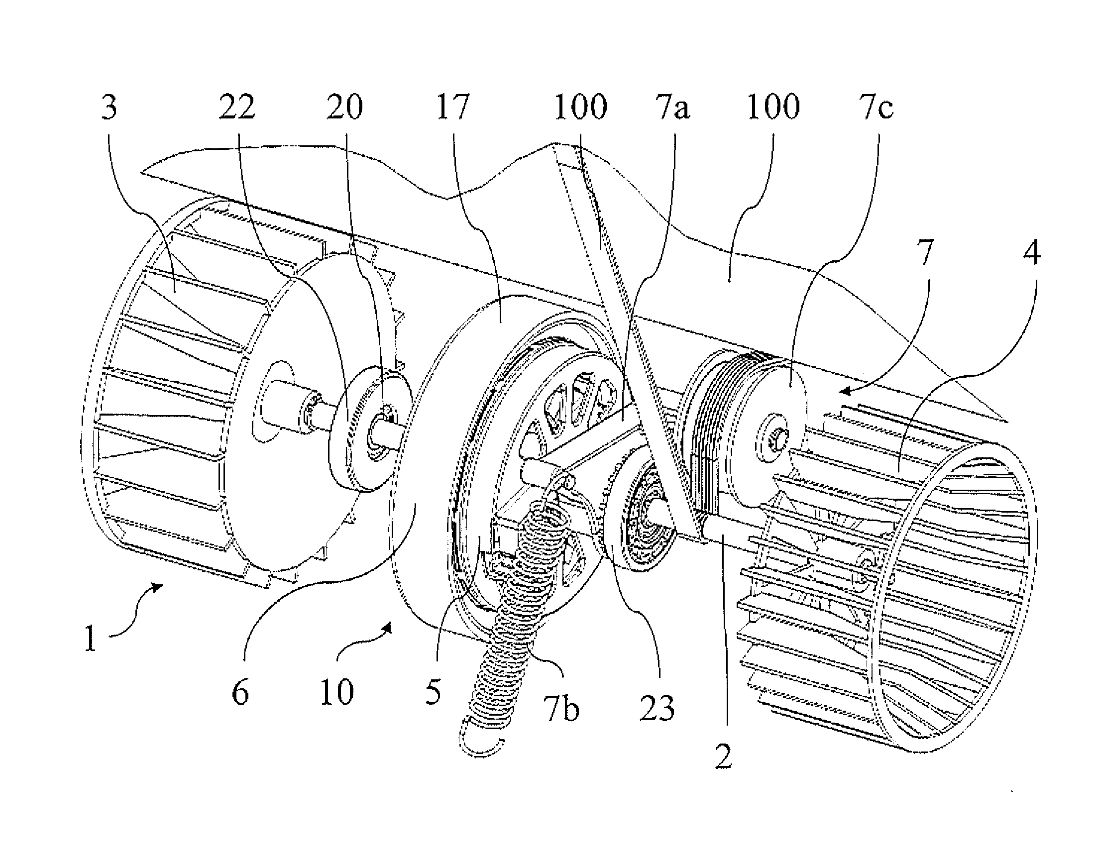
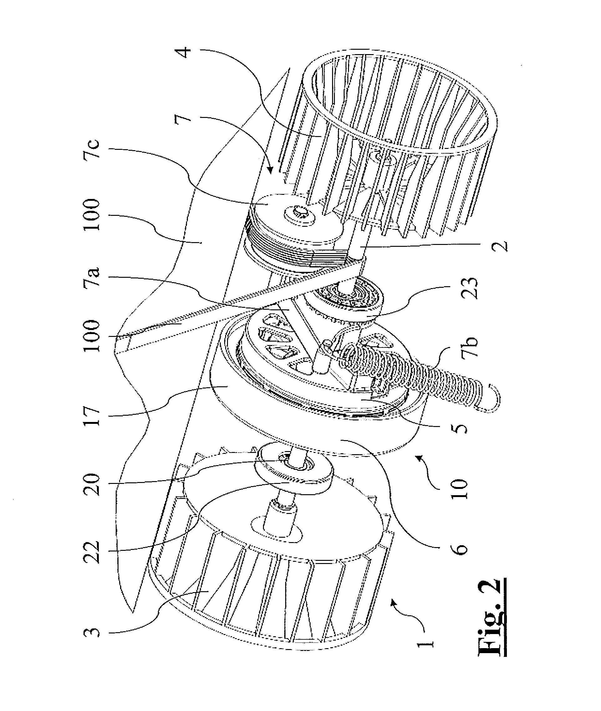
[0041]Referring to the accompanying drawings, 1 denotes generically the motor-bushings assembly of a laundry dryer machine 102 of the condenser type.

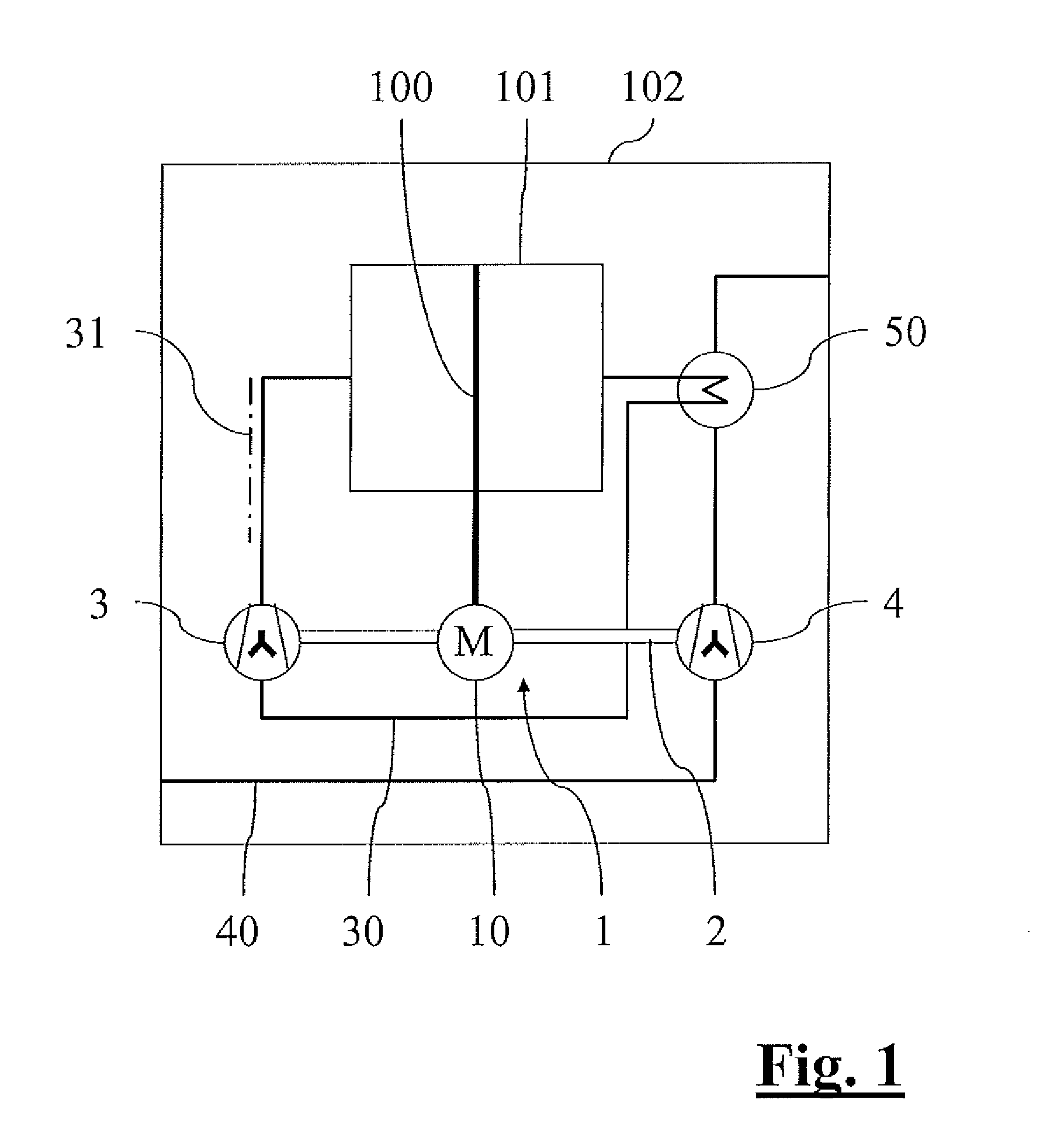
[0042]The known principle of operation of the condenser laundry dryer machine 102 can be seen from the constructional diagram shown in FIG. 1.

[0043]It comprises a rotating drum 101, rotatingly mounted in relation to a frame of the machine, intended to hold a load of laundry to be dried.

[0044]Inside the laundry dryer machine 102 a path of the hot air 30 and a path of the cold air 40 are defined, along which a fan for the hot air 3 and a fan for the cold air 4 are positioned respectively.

[0045]During operation of the appliance, the rotating drum 101 is maintained in rotation by means of an electric motor 10.

[0046]In the meantime, the fan for the hot air 3 maintains in circulation a flow of drying air via the path of the hot air 30. Said drying air is heated by means of appropriate heating means 31, and is then blown inside the rotating dr...


PUM


Abstract

A fans-motor assembly for condenser laundry dryer machine, of unusually low cost and overall dimensions, comprising: a drive shaft which can be associated in a rotating manner with a frame of a laundry dryer machine and designed to be connected by means of a transmission belt to a rotating drum thereof; a fan for the hot air and a fan for the cold air integral in rotation with said drive shaft and designed to convey respectively a flow of hot air and a flow of cold air along separate paths of said laundry dryer machine; a synchronous permanent magnet electric motor comprising an internal stator traversed by said drive shaft and an external rotor integral during rotation with said drive shaft.

Description

CROSS-REFERENCE TO RELATED APPLICATIONS[0001]The present application claims priority to European Patent Application No. 10425075.8, filed Mar. 18, 2010, the entirety of which is incorporated herein by reference.FIELD OF APPLICATION[0002]The present invention relates, in its more general aspect, to an assembly comprising the motor and the fans which determine the functioning of a laundry dryer machine.[0003]The technical field of the invention therefore relates to laundry dryer machines, and more particularly the specific field of laundry dryer machines of the condenser type.[0004]It should be noted that the generic term laundry dryer used in the present description is to comprise also machines which, in addition to the drying function, also integrate a function of washing of laundry.PRIOR ART[0005]Laundry dryer machines of various kinds and types are used both in the home and in industry to remove the moisture from items of clothing and / or other textile products, usually following a...

Claims


Application Information

Patent Timeline
Patent Type & Authority Applications(United States)
IPC IPC(8): F26B11/02
CPCF04D25/0606D06F58/08D06F58/24
Inventor MARIONI, ELIO
Owner ASKOLL HLDG SRL
Why Eureka
Try Eureka