

Refrigeration cycle apparatus
a technology of refrigerant cycle and compressor, which is applied in the direction of gas cycle refrigeration machines, refrigeration machines, heat pumps, etc., can solve the problems of difficult operation and achieve the effect of reducing the work of the low-pressure compressor, increasing the amount of power recovery in the expander, and reducing the refrigerant pressur
- Summary
- Abstract
- Description
- Claims
- Application Information
AI Technical Summary
Benefits of technology
Problems solved by technology
Method used
Image

Examples
first embodiment
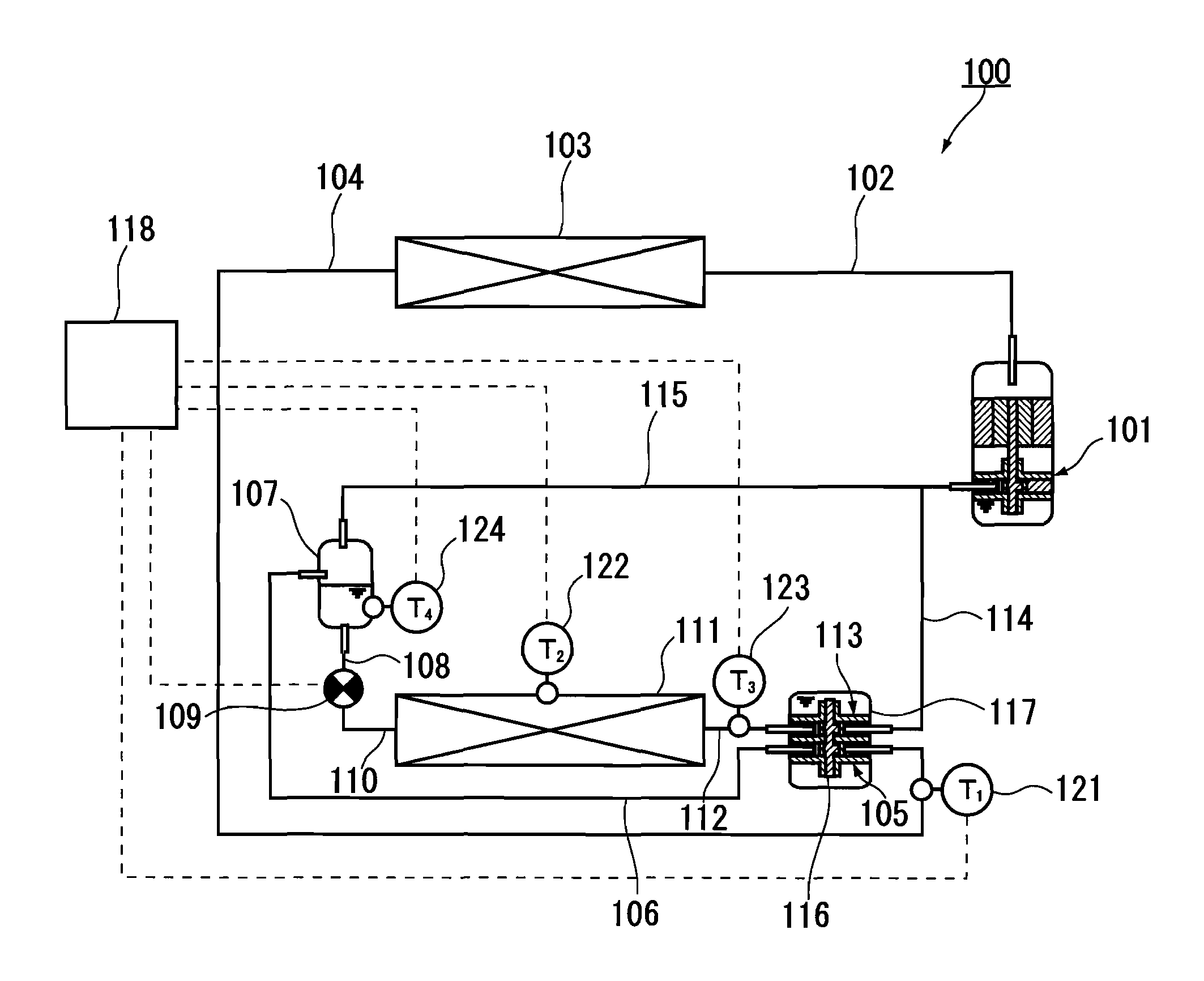
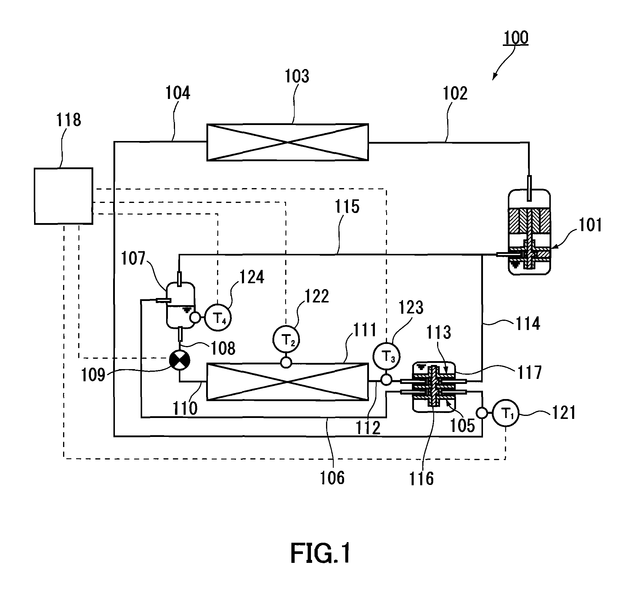
[0037]As indicated in FIG. 1, a refrigeration cycle apparatus 100 includes a high-pressure compressor 101, a radiator 103, an expander 105, a gas-liquid separator 107, an expansion valve 109, an evaporator 111 and a low-pressure compressor 113.
[0038]The low-pressure compressor 113 pre-compresses gas refrigerant that has been evaporated in the evaporator 111. The high-pressure compressor 101 further compresses the refrigerant (working fluid) that has been pre-compressed in the low-pressure compressor 113. The expander 105 recovers power by allowing the refrigerant that has been cooled in the radiator 103 to expand. Further, the expander 105 is configured to allow the entire amount of the refrigerant that has been cooled in the radiator 103 to pass therethrough. That is, no bypass circuit is provided for allowing the refrigerant to flow bypassing the expander 105. Since the entire amount of the refrigerant contributes to power recovery, the effect of improving the COP (coefficient of ...
second embodiment
[0096]FIG. 9 is a configuration diagram indicating a refrigeration cycle apparatus according to the second embodiment of the present invention. A refrigeration cycle apparatus 500 of this embodiment has a configuration similar to that of the refrigeration cycle apparatus 100 according to the first embodiment (see FIG. 1). This embodiment differs from the first embodiment in that a temperature sensor 520 is provided and in how the controller 118 carries out control. Hereinafter, the same functional components each are denoted by the same referential numeral, and the description thereof is omitted.
[0097]As indicated in FIG. 9, the refrigeration cycle apparatus 500 includes the temperature sensor 520 for detecting the discharge refrigerant temperature of the high-pressure compressor 101. In the same manner as in the first embodiment, the temperature sensor 122 also is provided for detecting the refrigerant evaporation temperature in the evaporator 111. The controller 118 controls the o...
third embodiment
[0102]FIG. 11 is a configuration diagram indicating a refrigeration cycle apparatus according to the third embodiment of the present invention. A refrigeration cycle apparatus 700 has a configuration similar to that of the refrigeration cycle apparatuses described in the first embodiment and the second embodiment. This embodiment differs from the first embodiment in that a high-pressure compressor 701, a low-pressure compressor 713 and an expander 705 are accommodated in a common closed casing 717.
[0103]As indicated in FIG. 11, in the refrigeration cycle apparatus 700, the high-pressure compressor 701, the low-pressure compressor 713 and the expander 705 are disposed in the single closed casing 717 from above in this order. The low-pressure compressor 713 and the expander 705 are connected by a shaft 716 so as to be capable of transmitting power. In the bottom of the closed casing 717, oil is stored. The space above the oil level is filled with a discharge refrigerant from the high-...
PUM
 Abstract
Description
Claims
Application Information