Electronic motor actuators brake inhibit for aircraft braking system

Inactive Publication Date: 2011-09-22
HYDRO AIRE INC
View PDF17 Cites 62 Cited by
  • Summary
  • Abstract
  • Description
  • Claims
  • Application Information

AI Technical Summary

Benefits of technology

[0006]Briefly, and in general terms, the present invention provides for a system and a method for conditionally inhibiting selected ones of a plurality of electric motor-actuators associated with an aircraft wheel brake, in which the capacity for full commanded braking is retained at all times. Conditionally inhibiting electrically actuated brakes utilizing multiple electric motor-actuators per brake according to the present invention can safely and successfully reduce the wear, and hence the cost, of utilizing electric motor-actuators. Reliability of the electric motor-actuators can be improved because individual electric motor-actuators would be subjected to fewer actuation cycles over a given period of time. In addition, conditionally inhibiting electrically actuated brakes utilizing multiple electric motor-actuators per brake according to the present invention ensures that the pedal “feel” remains unchanged, as compared with activation of all electric motor-actuators during braking. This also ensures that the amount of braking effort done by the electric brakes remains const

Problems solved by technology

One disadvantage of electrically actuated braking systems is that the electric motor-actuators are relatively expensive compared to the cost of hydraulic braking systems.
Particularly with aircraft braking systems that operate in a challenging environment with many wear cycles, such electrically actuated braking systems require periodic maintenance or overhaul to repair or refu

Method used


Image

  • Electronic motor actuators brake inhibit for aircraft braking system
  • Electronic motor actuators brake inhibit for aircraft braking system
  • Electronic motor actuators brake inhibit for aircraft braking system

Examples


Embodiment Construction

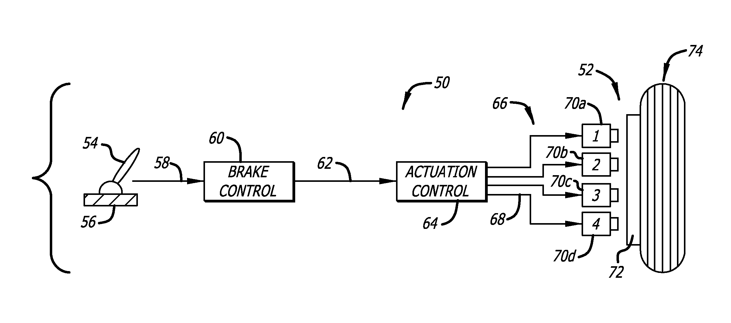
[0022]While the use of electrically actuated brakes in aircraft and other vehicles eliminates some disadvantages associated with the use of hydraulic brakes, the accumulated costs of utilizing multiple electric motor-actuators in electrically actuated braking systems, owing to the costs of periodic maintenance, repair and replacement of worn parts hydraulic braking systems, and particularly heavy usage in aircraft braking systems that operate in challenging environments, can be significant.

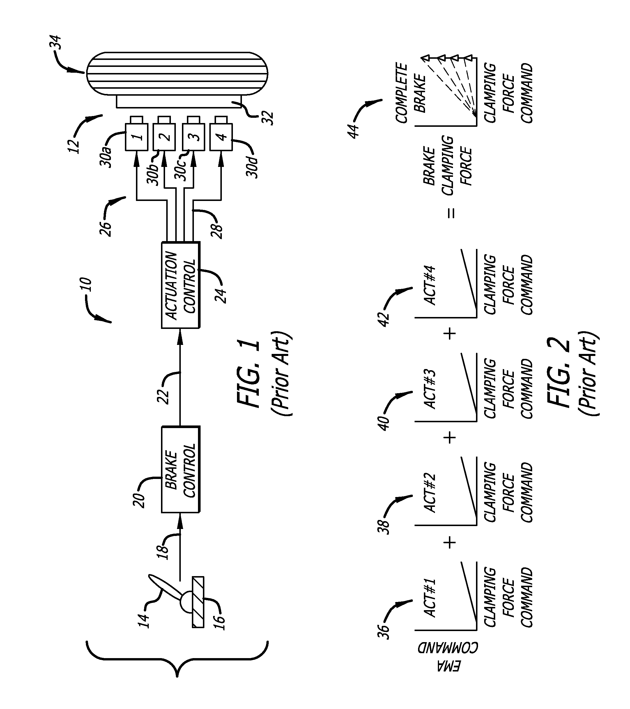
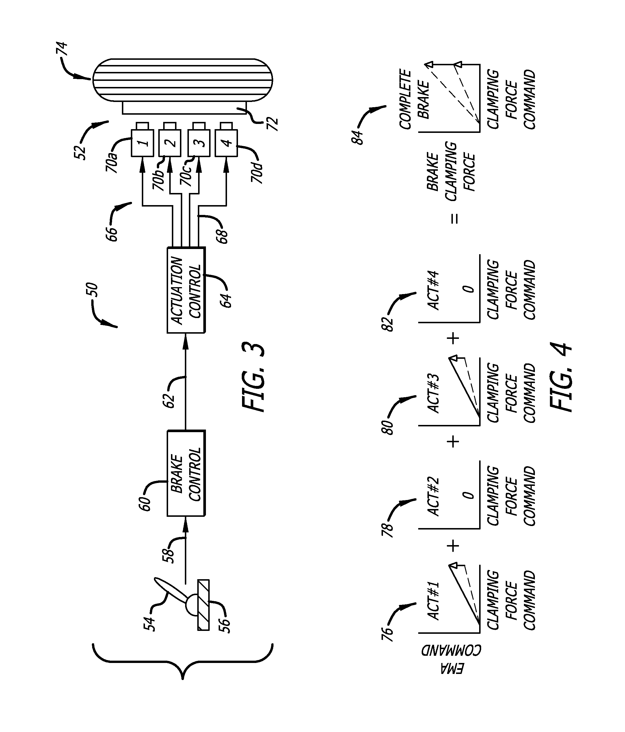
[0023]As is illustrated in FIG. 1, a prior art system 10 for controlling an electrically actuated brake system 12 typically includes an aircraft brake pedal 14 operated by a pilot (not shown), and a microcontroller 16 associated with the aircraft brake pedal. The microcontroller reads the position of the aircraft brake pedal and generates a brake pedal command signal 18, which is received by a brake system control unit (BSCU) 20. The brake system control unit in turn generates a commanded clamping...


PUM


Abstract

A brake system control unit controls one of first and second portions of a wheel brakes electric brake actuators to activate one of the first and second portions of the actuators and deactivate the other during an inhibited braking mode. The control unit controls the activated portion of the brake actuators to generate a braking force greater than the commanded braking force of the brake pedal command, such as twice the commanded braking force, to compensate for the deactivated portion of the brake actuators. The inhibited braking mode is discontinued during emergency braking when the commanded braking force is greater than or equal to a predetermined braking force. The inhibited braking mode is also discontinued when failure of one or more brake actuators is detected.

Description

BACKGROUND OF THE INVENTION[0001]The present invention generally relates to electric braking systems and more particularly pertains to systems for selectively inhibiting electric motor actuators for aircraft electric braking systems.[0002]The use of electrically actuated brakes in aircraft and other vehicles is becoming increasingly common. Braking force is typically generated by the pressurization of piston actuators that are configured to compress a brake disk stack between a pressure plate and a backing plate to thereby cause the friction surfaces of adjacent disks to engage one another. Electrically actuated brakes typically apply such a clamping force to a brake pressure plate with electric motor-actuators (EMAs) instead of hydraulic pistons. This eliminates certain disadvantages associated with hydraulic brakes, such as hydraulic leaks, air entrainment in hydraulic fluid, loss of hydraulic fluid causing loss of multiple brakes, a potential for hydraulic fluid fires, and the li...

Claims


Application Information

Patent Timeline
IPC IPC(8): B64C25/44F16D65/34G06F19/00B60T13/74F16D65/28
CPCB60T2270/402B60T8/1703
Inventor DEVLIEG, GARRETT H.
Owner HYDRO AIRE INC
Why Eureka
Try Eureka