Image stabilization system

a technology of image stabilization and image tracking, which is applied in the direction of optical radiation measurement, instruments, printers, etc., can solve the problems of blurred images of moving objects, lack of clarity or detail, and image acquisition from moving platforms, so as to improve image resolution and improve image tracking

Active Publication Date: 2011-09-22
TELEDYNE FLIR LLC
View PDF28 Cites 18 Cited by
  • Summary
  • Abstract
  • Description
  • Claims
  • Application Information

AI Technical Summary

Benefits of technology

[0006]The present teachings provide imaging systems in which an undedicated optical component—i.e., a component that would be present in the system even in the absence of image stabilization—is configured to undergo corrective motion and / or otherwise to correct image data, and thus to function as a stabilization component. The stabilization component may be a mirror and / or a lens, and a positioner may be provided to tilt, rotate, and / or otherwise precisely adjust the position and orientation of the stabilization component to improve image resolution, compensate for platform motions such as platform vibration, and / or improve image tracking. Because an undedicated optical component functions as the stabilization component, the stabilization occurs upstream, rather than downstream, from separation (if any) of the incoming image data into two or more beams. As a result, only one stabilization component is required regardless of whether the system is configured to split the image data into multiple data channels, and imaging systems as described herein therefore may be particularly well-suited for integration into a shared-aperture imaging system. In some embodiments, the coefficients of thermal expansion of selected system components—including optics, optical support structures, and / or positioners—may be matched.

Problems solved by technology

Unfortunately, images produced by such imaging systems may suffer from a variety of shortcomings, potentially causing a lack of clarity or detail in the images on a scale where increased clarity is desired.
For example, images acquired from a moving platform, such as an airborne platform mounted to an airplane, a helicopter, or a satellite, may be blurred due to vibrational and / or other motions of the platform.
Alternatively, or in addition, images of a moving object may be blurred due to an inability of the imaging system to track or keep pace with the moving object sufficiently effectively.
However, the addition of the dedicated stabilization components may require undesirable expense, and may take up otherwise needed space in an instrument.
In this arrangement, image data reach the stabilization component after it already has been magnified or demagnified by other components of the system, and this downstream location of the stabilization component may give rise to additional drawbacks.
For example, relatively large motions of the stabilization component may be necessary to accomplish the desired image correction, and this may be difficult to achieve with precision.
Additionally, in cases where an incoming signal is split into multiple separate signals to produce more than one distinct image, multiple dedicated stabilization components may be required, compounding the extra expense and space required for stabilization of acquired image data.

Method used


Image

  • Image stabilization system
  • Image stabilization system
  • Image stabilization system

Examples


example 1

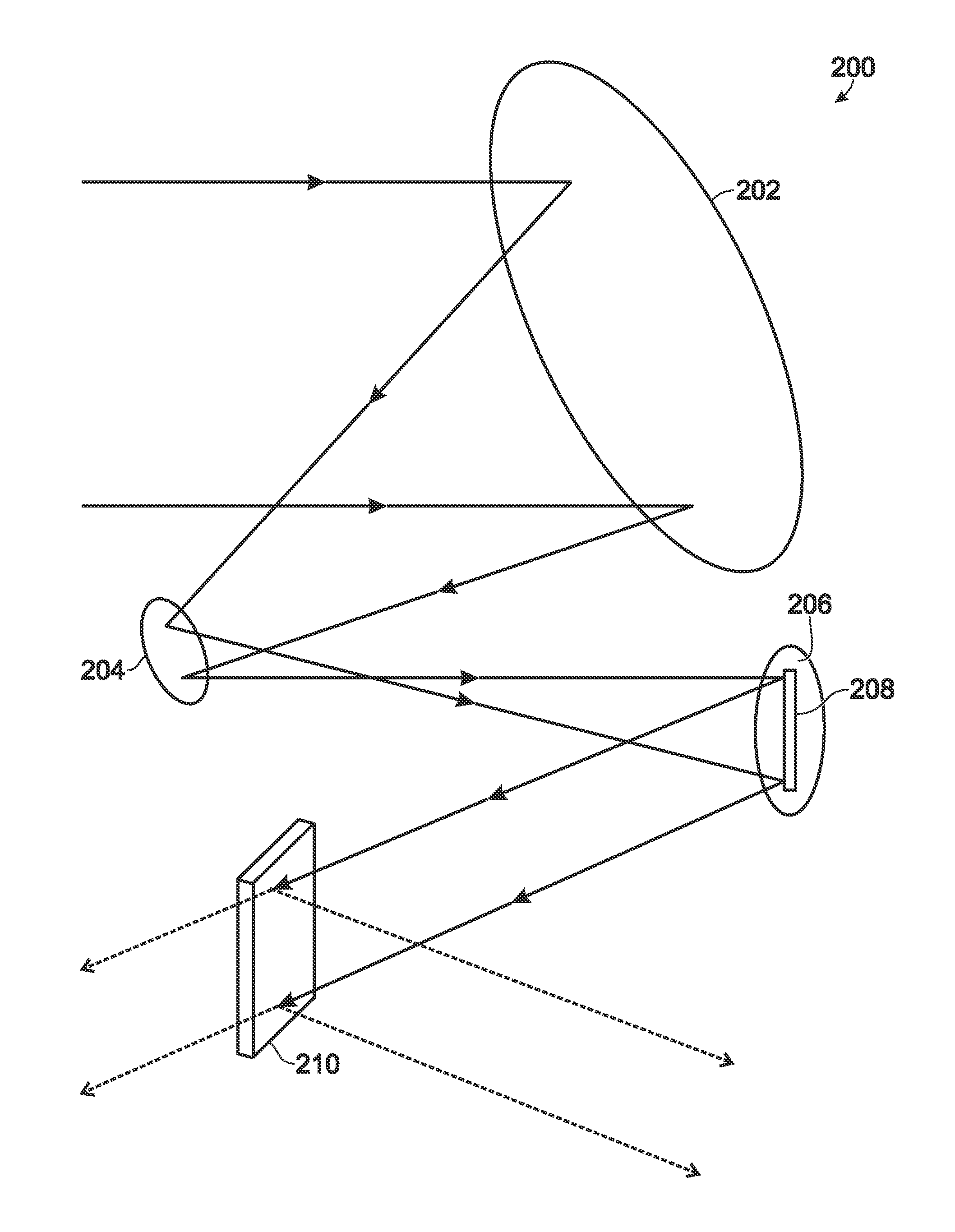
[0078]This example describes an exemplary off-axis, three-mirror assembly imaging system, constructed in accordance with aspects of the present teachings; see FIG. 8.

[0079]FIG. 8 shows a portion of an exemplary three-mirror assembly imaging system 200. The system includes a primary mirror 202, a secondary mirror 204, and a tertiary mirror 206 functioning as an undedicated optical stabilization component. The position of the tertiary mirror may be adjusted by a positioner 208, such as a piezoelectric positioner, as described above. In other embodiments, the position of the primary and secondary mirrors, or combinations of the primary, secondary, and tertiary mirrors, may be adjusted by suitable positioners. Here, unstabilized image data, represented as rays by the directional arrows arriving at primary mirror 202, may be stabilized by the motions of tertiary mirror 206. Specifically, positioner 208 is configured to control the position and orientation of the tertiary mirror 206 in ti...

example 2

[0080]This example describes several exemplary multi-band energy channels, suitable for use in an imaging system constructed in accordance with aspects of the present teachings; see FIGS. 9-11. Imaging energy can be stabilized and / or dithered, in accordance with the present disclosure, using virtually any multi-band energy channel that includes at least one optical element suitable for selective movement. In general, reflective elements, such as mirrors, are particularly well suited to move to stabilize and / or dither imaging energy. In the following exemplary channels, stabilization and / or dithering may be effected by selectively moving any of the illustrated optical components, relative to other components of the same channel.

[0081]FIG. 9 shows an exemplary Cassegrain telescope 300. The telescope includes a primary mirror 302, a secondary mirror 304, a tertiary mirror 306, and a quaternary mirror 308. The optical path for various incident light rays is shown by directional arrows 3...

example 3

[0084]This example describes additional image stabilization systems, constructed in accordance with aspects of the present teachings. Specifically, the systems described herein optionally may be combined with other systems for improving image acquisition and / or quality, including hardware and / or software systems, for example, as described in U.S. patent application Ser. No. 11 / 207,536, filed Aug. 19, 2005, which is incorporated herein by reference in its entirety for all purposes.


PUM


Abstract

Imaging systems in which an undedicated optical component—i.e., a component that would be present in the system even in the absence of image stabilization—is configured to undergo corrective motion and/or other correction of image data, and thus to function as a stabilization component. The stabilization component may be a mirror and/or a lens, and a positioner may be provided to tilt, rotate, and/or otherwise precisely adjust the position and orientation of the stabilization component to improve image resolution, compensate for platform motions such as platform vibration, and/or improve image tracking. Because an undedicated optical component functions as the stabilization component, the stabilization occurs upstream, rather than downstream, from separation (if any) of the incoming image data into two or more beams. As a result, only one stabilization component is required regardless of whether the system is configured to split the image data into multiple data channels, and imaging systems as described herein therefore may be particularly well-suited for integration into a shared-aperture imaging system. In some embodiments, the coefficients of thermal expansion of selected system components—including optics, optical support structures, and/or positioners—may be substantially the same or closely matched.

Description

CROSS-REFERENCES TO RELATED APPLICATION[0001]This application is a continuation-in-part of U.S. patent application Ser. No. 11 / 393,448, filed Mar. 29, 2006, now U.S. Pat. No. 7,862,188, which in turn is based upon and claims the benefit under 35 U.S.C. §119(e) of U.S. Provisional Patent Application Ser. No. 60 / 696,306, filed Jul. 1, 2005. Both of these priority applications are incorporated herein by reference in their entireties for all purposes.INTRODUCTION[0002]Imaging systems can be used, directly or indirectly, to convert radiation into images. For example, visible-light digital cameras can translate visible light into a digital signal that can be used to produce a visible image, infrared-radiation digital cameras can translate infrared radiation into a digital signal that can be used to produce an infrared image, and so forth for other wavelength regimes. Unfortunately, images produced by such imaging systems may suffer from a variety of shortcomings, potentially causing a lac...

Claims


Application Information

Patent Timeline
Patent Type & Authority Applications(United States)
IPC IPC(8): G01J5/08G02B27/64G02B7/198
CPCG02B17/06G02B27/644G02B27/648H04N5/2328G03B15/006H04N5/23258G03B5/00H04N23/6812H04N23/685
Inventor LUTY, CLIFFORD J.DICKERSON, BRUCE A.ELLISON, BRUCEMILLER, JOHN L.
Owner TELEDYNE FLIR LLC
Why Eureka
Try Eureka