
Power converter device

a power converter and converter technology, applied in the direction of dynamo-electric converter control, motor/generator/converter stopper, dynamo-electric gear control, etc., can solve the problems of inability to obtain the desired braking power, long time, and a large amount of braking power, and achieve stable braking power. , the effect of large braking power

Active Publication Date: 2011-09-22
HITACHI IND EQUIP SYST CO LTD
View PDF24 Cites 5 Cited by
  • Summary
  • Abstract
  • Description
  • Claims
  • Application Information

AI Technical Summary

Benefits of technology

[0015]Thus, an object according to the present invention, for dissolving such the problems as mentioned above, is to provide a stopping method for enabling a motor to obtain a stable braking power even when rotating at a high speed, and also to obtain a large braking power even when rotating at a low speed, without necessity of a rotation speed detecting means of the motor or an external braking, as well as, to output a desired stopping torque after stoppage thereof.
[0017]According to the present invention, there can be obtained a power converter device for driving a permanent magnet synchronous motor, i.e., enabling to obtain a stable braking power even when it is rotating at a high speed, and / or a large braking power even when it is rotating at a low speed, without necessity of a rotation speed detecting means of the motor or an external brake, as well as, outputting a desired stopping torque even after stoppage thereof.

Problems solved by technology

When cutting off the power supply to stop the permanent magnet synchronous motor, since braking power is determined by magnitude of the axial load and / or the air resistance, therefore it is impossible to obtain a desired braking power, and thereby brining about a drawback that it takes a long time until the stoppage thereof.
When decelerating and stopping the permanent magnet synchronous motor through the regenerative braking, it is necessary to provide a control means for decelerating and stopping, separately, and there is also possibility of loss of synchronization, in particular, when decelerating it abruptly.
And, in a use thereof within a fan and a pump, etc., there is also a problem, i.e., necessitating detection or estimation of the rotation speed and induction voltage thereof, as well as, provision of a special starting means, separately, so as to execute the starting thereof with using of those, in particular, when the permanent magnet synchronous motor is rotating under the free-run condition.
When decelerating and stopping the permanent magnet synchronous motor through the DC braking, in particular, when it is rotating at the high speed, the excessive current is generated, and this results into demagnetization and burning of that motor, or breakage of the switching element(s) of the power converter device.
Also, there is a problem that, if the power converter is provided with the protection with using the over-current, the output is cut off because of that protection, and that the permanent magnet synchronous motor is brought into the free-run condition; therefore, it is impossible to execute the DC braking with stability.
When decelerating and stopping the permanent magnet synchronous motor through the reversed phase braking, the braking force is in shortage, in particular, when it is rotating at the low speed, and then it takes a long time until when it is decelerated down to a desired speed and the stoppage thereof.
Also, when it is rotating at the high speed, the excessive current is generated, and this results into demagnetization and burning of that motor, or breakage of the switching element(s) of the power converter device.
And also, if the power converter is provided with the protection with using the over-current, the output is cut off because of that protection, and that the permanent magnet synchronous motor is brought into the free-run condition; i.e., there is a problem that it is impossible to execute the DC braking with stability.

Method used


Image

  • Power converter device
  • Power converter device
  • Power converter device

Examples


embodiment 1

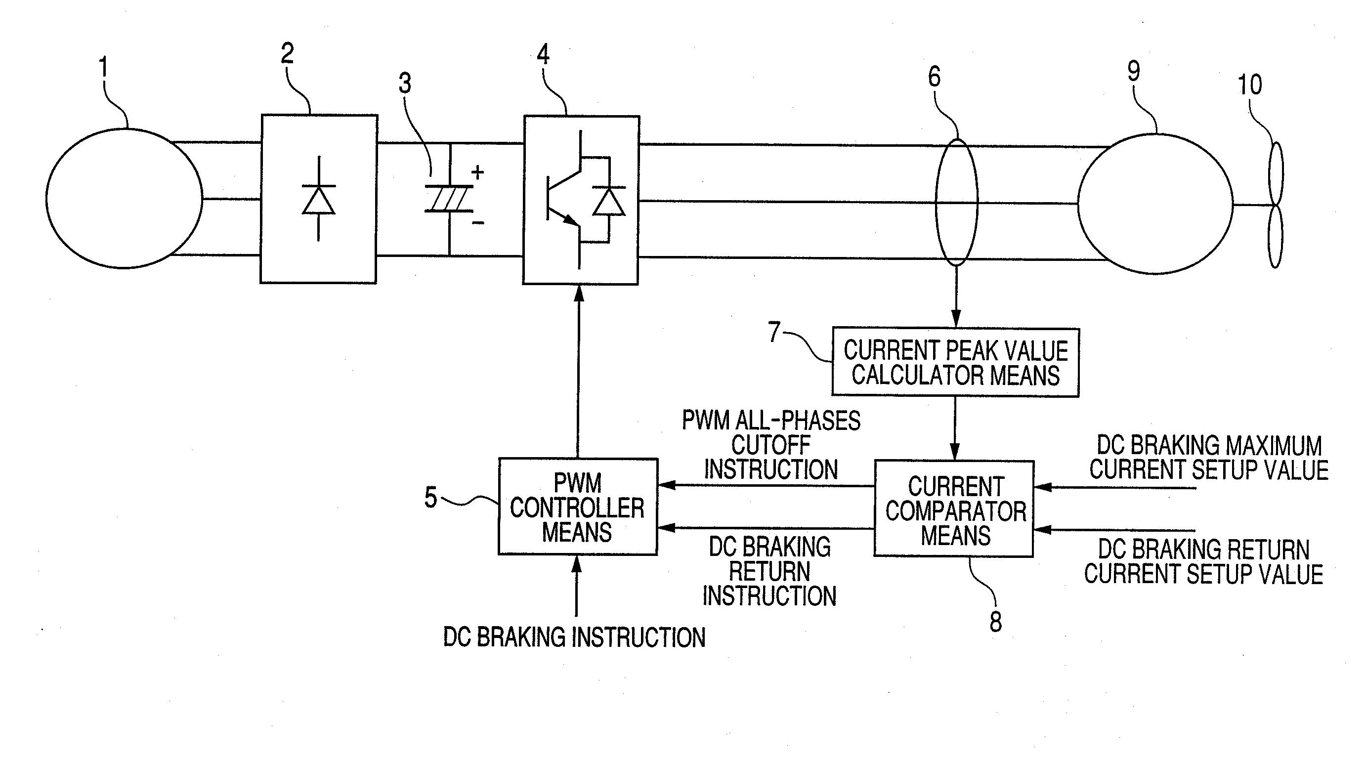
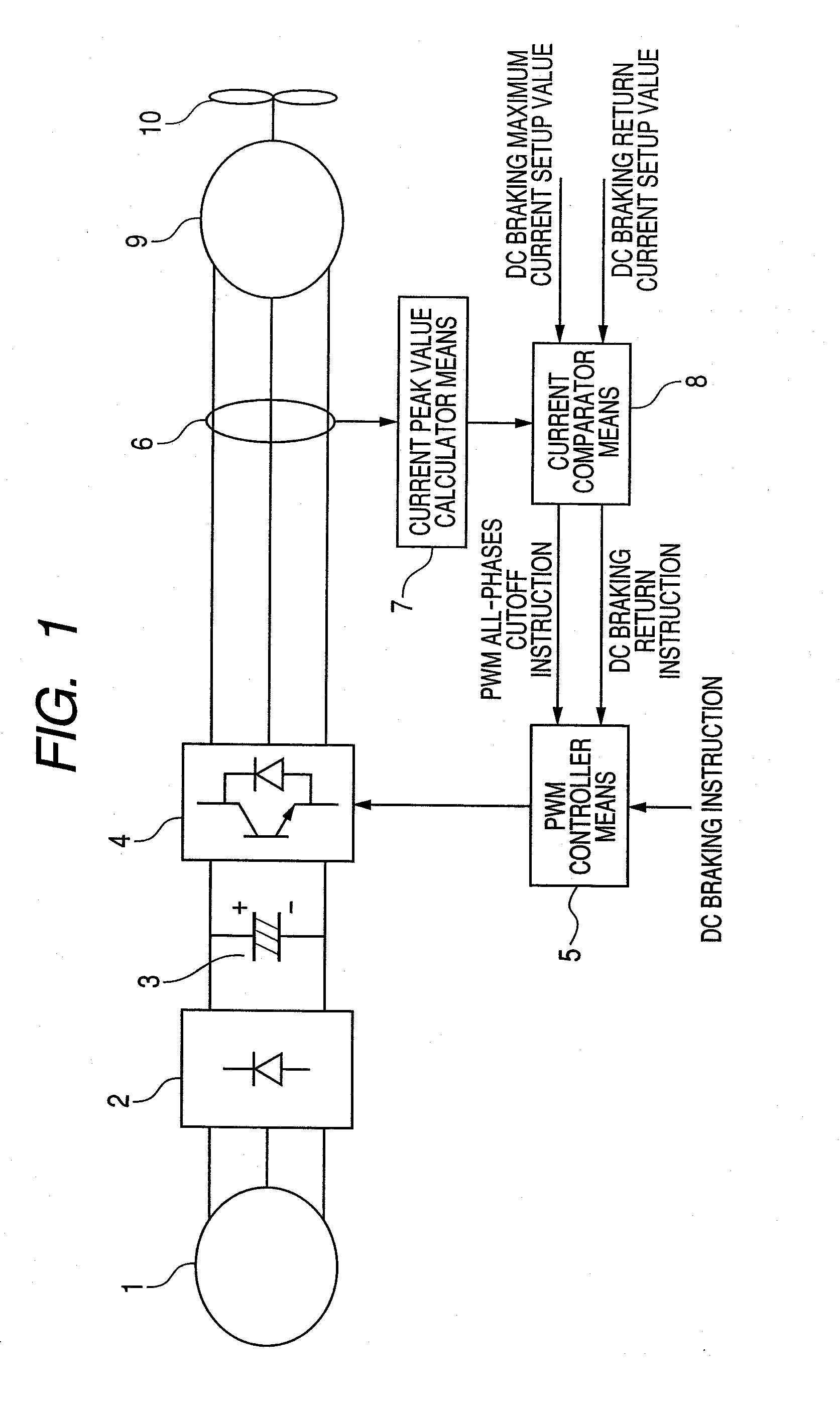
[0023]FIG. 1 is a block circuit diagram for showing an embodiment according to the present invention. AC voltage generating from a AC power source 1 is rectified within a rectifier circuit 2, and it is smoothed by a smoothing circuit 3. DC current smoothed is converted to AC voltage through a switching circuit 4, thereby to be applied to a permanent magnet synchronous motor 9.

[0024]A PWM controller means 5 controls ON and OFF of the switching circuit 4, so that random voltage can be applied to the permanent magnet synchronous motor 9.

[0025]A current detector means 6 detects phase current running through the permanent magnet synchronous motor 9. Or, a shunt resistor may be provided on a negative electrode side of the smoothing circuit 3, so as to estimate the phase current from the current flowing through this shunt resistor. A fan 10 is attached onto a shaft of the permanent magnet synchronous motor 9.

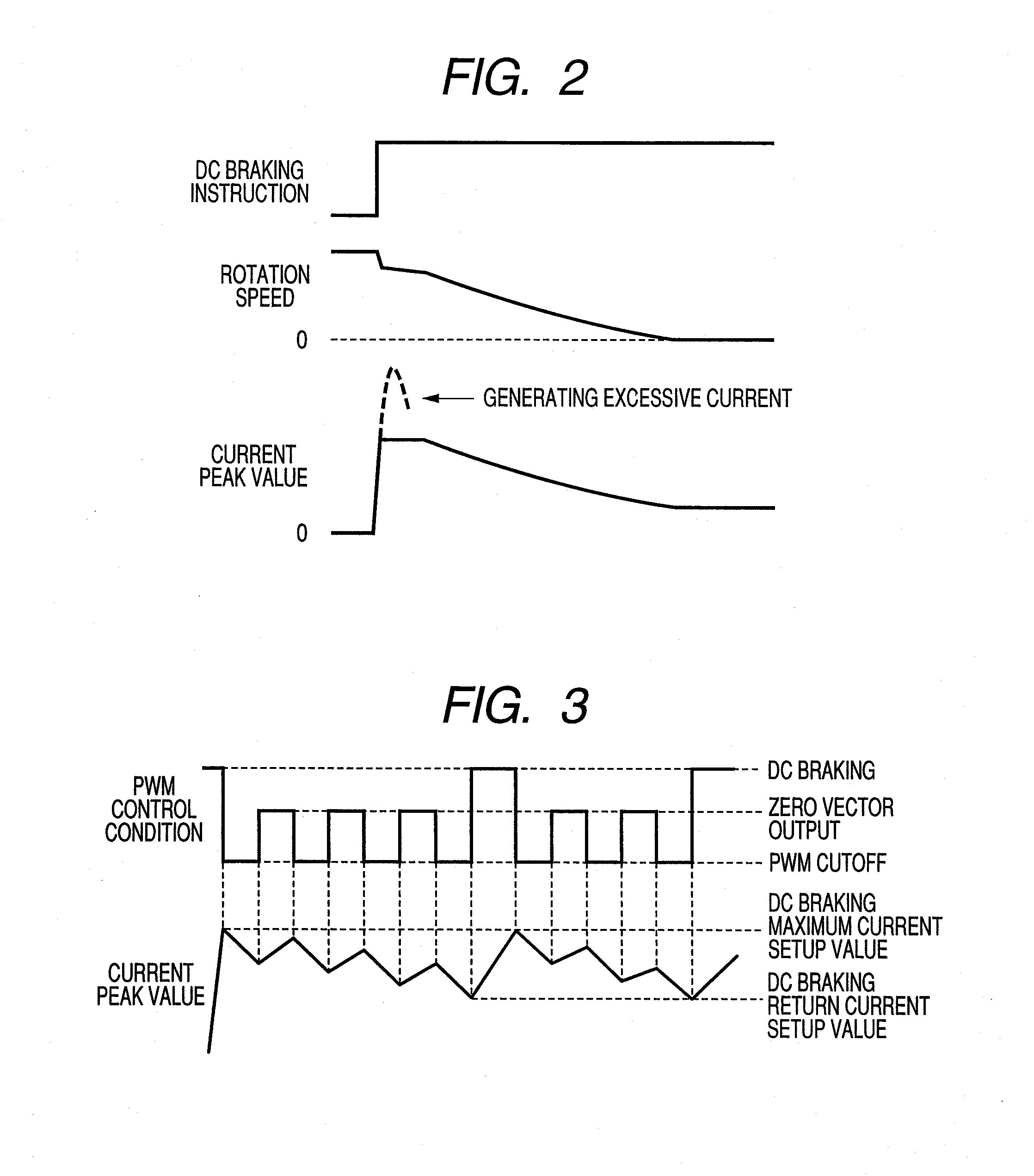
[0026]FIG. 2 shows an example of waveforms of rotation number and current when the...


PUM


Abstract

A power converter device for achieving a stable braking operation, preventing excessive current to flow therein, when conducting DC braking on a permanent synchronous motor, comprises: a switching circuit for converting DC to AC; a PWM controller means, for controlling ON or OFF of said switching circuit; a means for detecting or estimating current flowing through a permanent magnet synchronous motor; and a means for executing DC braking of said permanent magnet synchronous motor, wherein there are provided a DC braking maximum current setup value, which is determined from an outside or is determined in advance within an inside, and a PWM all-phases cutoff function and a zero vector output function within said PWM controller means, within said PWM controller means, whereby the PWM all-phases cutoff and the zero vector output are repeated within said PWM controller means, if a current value, which is obtained by said means for detecting or estimating the current, exceeds said DC braking maximum current setup value, when running DC current to the permanent magnet synchronous motor, so as to execute DC braking for obtaining a braking power.

Description

[0001]This application relates to and claims priority from Japanese Patent Application No. 2009-252573 filed on Nov. 4, 2009, the entire disclosure of which is incorporated herein by reference.BACKGROUND OF THE INVENTION[0002]The present invention relates to a power converter device.[0003]Conventionally, when stopping rotation of a permanent magnet synchronous motor, it is common to stop power supply thereto, simply, and thereby stopping it naturally, with using an axial load and air resistance thereof.[0004]When there is necessity of stopping the permanent magnet synchronous motor, abruptly, it is decelerated for a predetermined time or down to a predetermined ration speed, through regenerative braking, and thereafter it is stopped naturally.[0005]Or, there is already known a method, so-called a direction current braking (or DC braking) of turning ON, either one (1) phase or two (2) phases on a positive (+) electrode side (s) of a switching circuit, with a negative side of other ph...

Claims


Application Information

Patent Timeline
IPC IPC(8): H02P3/18H02P3/00H02P3/22H02P21/22H02P21/36H02P27/08
CPCH02P3/24H02P3/18H02P25/021H02P25/024H02M7/48H02P27/08
Inventor ONUMA, YUSAKUARAO, YUSUKE
Owner HITACHI IND EQUIP SYST CO LTD
Learn More