Mounting structure for mini pci-e equipment and a computer using the same

a technology of mounting structure and mini pci-e equipment, which is applied in the direction of electrical apparatus construction details, electrical apparatus casings/cabinets/drawers, instruments, etc., can solve the problems of mini pci-e equipment occupying more space on the motherboard inevitably, the performance improvement of digital signals is becoming bottleneck, and the instability of mini pci-e equipment, etc., to achieve the effect of improving heat dissipation performance and reducing

Inactive Publication Date: 2011-09-22
PC PARTNER DONGGUAN
View PDF7 Cites 39 Cited by
  • Summary
  • Abstract
  • Description
  • Claims
  • Application Information

AI Technical Summary

Benefits of technology

[0026]The mounting structure for Mini PCI-E equipment and the computer using the same in accordance with the present invention could significantly reduce the area on the motherboard occupied by the Mini PCI-E equipment via setting the Mini PCI-E slots and the fixing bracket perpendicular to the motherboard. The above mounting structure could also improve the performance of heat dissipation of the Mini PCI-E equipment. In addition, the mounting structure in accordance with the present invention could be fit for different types of Mini PCI-E equipment.

Problems solved by technology

With the development of computer technology, transmission of digital signal is becoming bottleneck of performance improvement for communications between the computer and the peripheral equipment.
As the Mini PCI-E equipment is assembled on and parallel to the motherboard, the Mini PCI-E equipment occupies more space on the motherboard inevitably, which is contrary to the concept of small computers.
As the Mini PCI-E equipment is installed close to the motherboard, it is not conducive for heat dissipation which would make the Mini PCI-E equipment working unstable.
In addition, when the slot of the Mini PCI-E equipment is parallel to the motherboard, it makes space for pluging-and-socketing the Mini PCI-E equipment smaller, so that make it hard to install the Mini PCI-E equipment.

Method used


Image

  • Mounting structure for mini pci-e equipment and a computer using the same
  • Mounting structure for mini pci-e equipment and a computer using the same
  • Mounting structure for mini pci-e equipment and a computer using the same

Examples


first embodiment

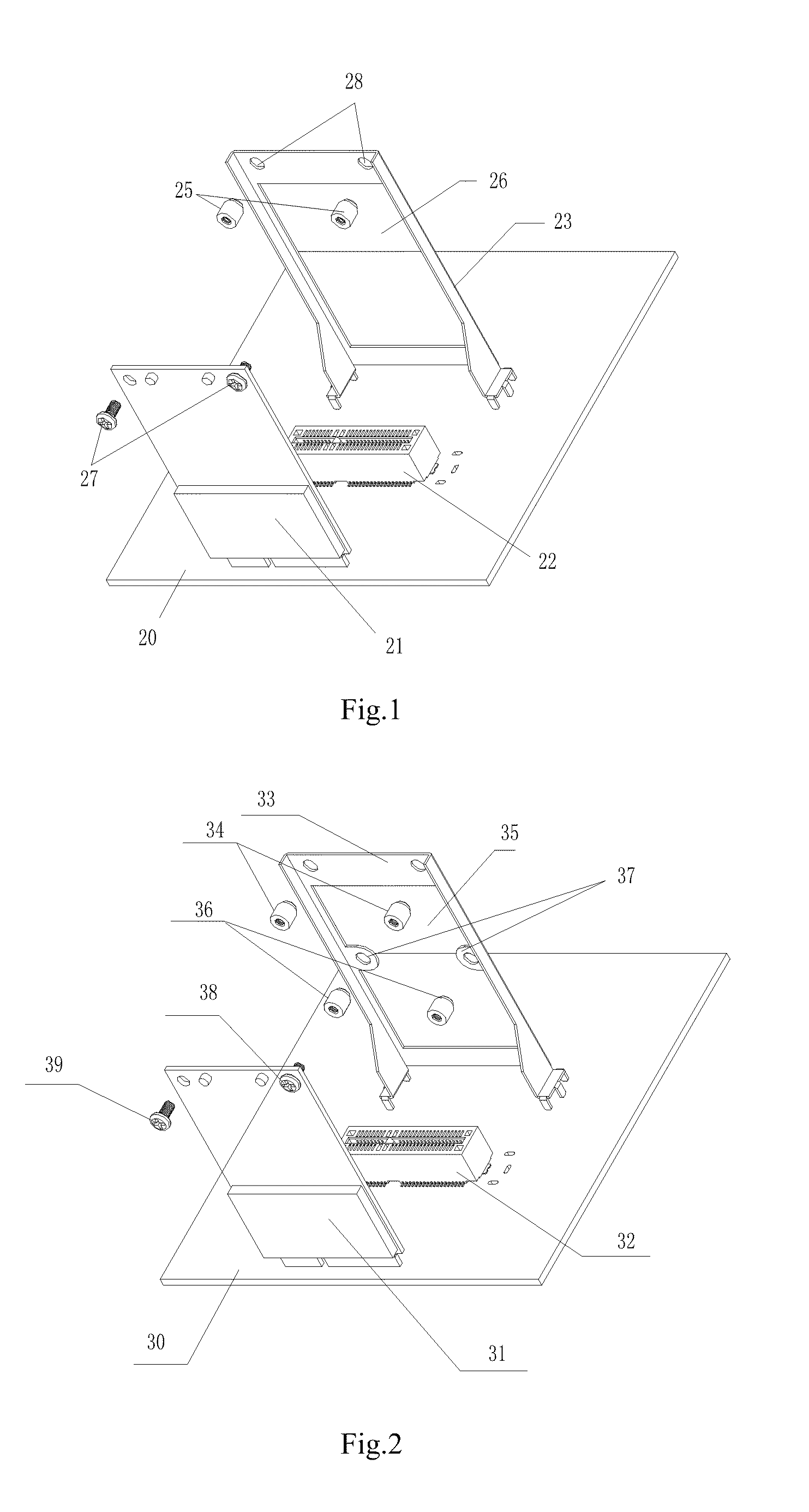
[0037]As shown in FIG. 1, in the present invention, the mounting structure for the Mini PCI-E equipment includes a Mini PCI-E slot 22 and a fixing bracket 23. The Mini PCI-E slot 22 is welding on the surface of a motherboard 20 with the opening upward and perpendicular to the motherboard 20. The fixing bracket 23 is close to the Mini PCI-E slot 22 and fixed vertically on the motherboard 20.

[0038]The fixing bracket 23 is provided with a fixing device which includes at least two fixing holes 28, two bolts 25 and two nuts 27 matching the bolts 25. The two fixing holes 28 are at the same height. In present embodiment, the two fixing holes 28 are at the top of the fixing bracket 23. The two bolts 25 are fixed (riveted, for example) on the two fixing holes 28 respectively. The Mini PCI-E slot 22 is welded to the surface of the motherboard 20 in the mode of SMT or DIP. The fixing bracket 23 is welded on the motherboard 20 in the mode of DIP. The two bolts 25 are riveted on the fixing brack...

second embodiment

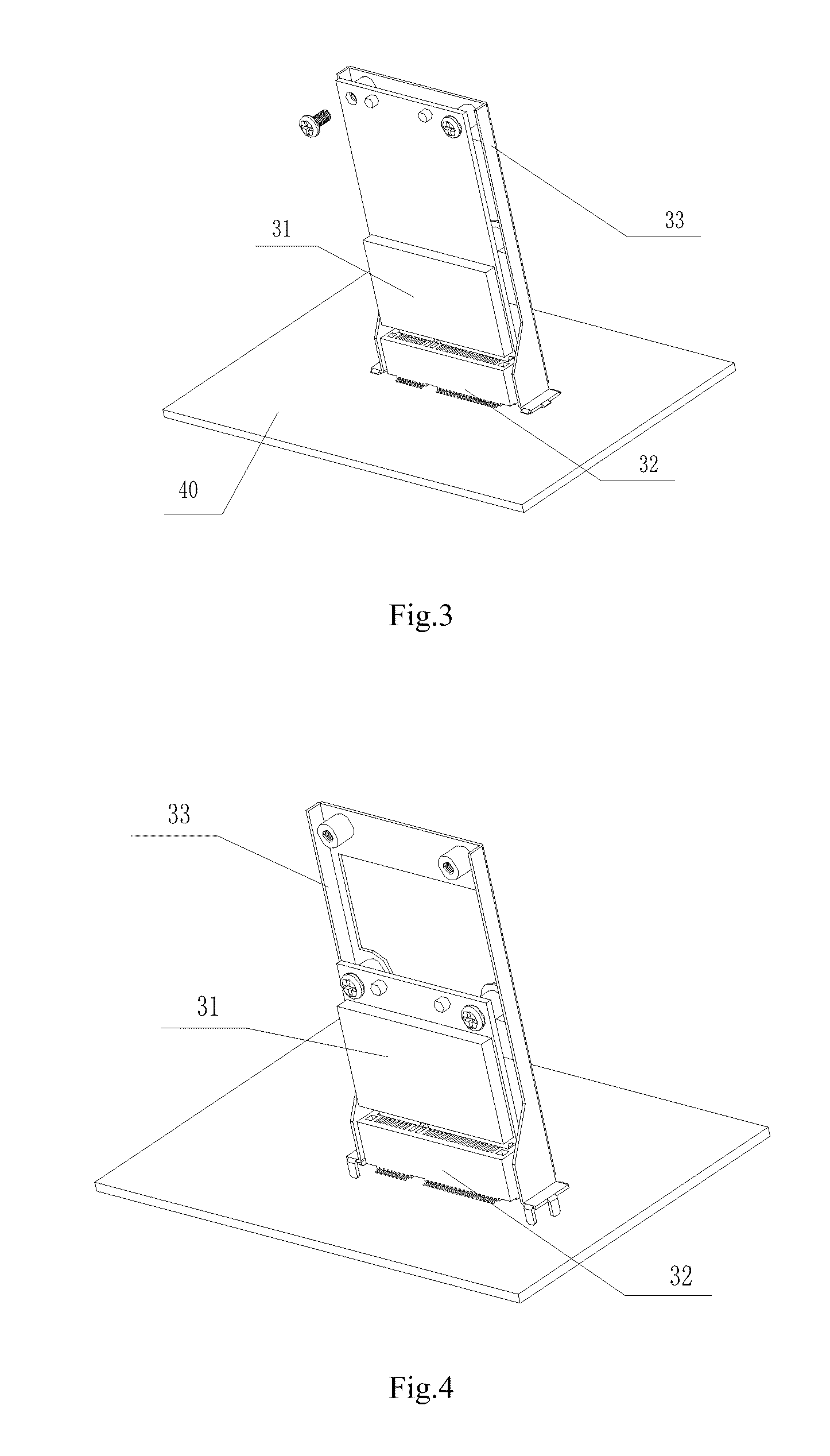
[0041]As shown in FIG. 2, the mounting structure for Mini PCI-E equipment in accordance with the present invention includes a Mini PCI-E slot 32 fixed on the motherboard 30 and a fixing bracket 33 arranged close to the Mini PCI-E slot 32. The fixing bracket 33 is provided with a first fixing device and a second fixing device located at a different height from the first fixing device. The first fixing device includes at least two nuts 34 at the same height. The second fixing device includes at least two nuts 36 at the same height. The Mini PCI-E slot 32 is welded on the upper surface of the motherboard 30 in the mode of SMT or DIP while the fixing bracket 33 is welded on the motherboard 30 in the mode of DIP. The first nuts 34 and the second nuts 36 are riveted on the fixing bracket 33.

[0042]Of course, in practice, the number of nuts in each fixing device can be adjusted according to actual needs. And one or more fixing devices can be provided to the fixing bracket in accordance with...

third embodiment

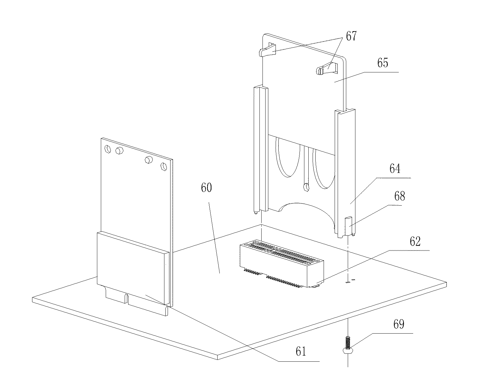
[0046]As shown in FIG. 5, the mounting structure in accordance with the present invention includes Mini PCI-E slots 62 and a fixing bracket. The Mini PCI-E slots 62 is welded on the surface of the motherboard 60 with the opening upward and perpendicular to the motherboard, while the fixing bracket is close to the Mini PCI-E slot and fixed vertically on the motherboard 60.

[0047]The fixing bracket includes a support frame 64 and a sliding board 65. The support frame 64 is provided with two sides at both ends of the Mini PCI-E slot 62. Each of the insides of the two sides of the sliding board 65 is provided with a vertical chute close to the Mini PCI-E slot 62. The sliding board 65 is plugged into the chute and the sliding board 65 is provided with a fixing device on the side facing the Mini PCI-E slot 62. The fixing device includes two snaps 67 at the same height. Otherwise, the fixing device may include two nuts at the same height (as the nuts shown in FIG. 1 and FIG. 2). Of course, ...


PUM


Abstract

The present invention relates to amounting structure for Mini PCI-E equipment is provided. The mounting structure comprises a Mini PCI-E slot and a fixing bracket, wherein the Mini PCI-E slot is welded on surface of a motherboard with an opening upward and perpendicular to the motherboard, the fixing bracket is close to the Mini PCI-E slot and fixed vertically on the motherboard. The fixing bracket includes a first fixing device which includes at least two mounting holes at the same height. The present invention also disclosed a computer using the above mounting structure. The mounting structure of the present invention could significantly reduce the area on the motherboard occupied by the Mini PCI-E equipment via setting the Mini PCI-E slots and the mounting bracket perpendicular to the motherboard. The above mounting structure could also improve the performance of heat dissipation of the Mini PCI-E equipment.

Description

CROSS REFERENCE TO RELATED PATENT APPLICATION[0001]The present application claims the priorities of the Chinese patent applications No. 201020134791.4 filed on Mar. 17, 2010, No. 201020134801.4 filed on Mar. 17, 2010 and No. 201020134809 filed on Mar. 17, 2010, which applications are incorporated herein by reference.FIELD OF THE INVENTION[0002]The present invention relates to a mounting structure for electronic equipment, and particularly, relates to a mounting structure for Mini PCI-E equipment and a computer using the same.BACKGROUND OF THE INVENTION[0003]With the development of computer technology, transmission of digital signal is becoming bottleneck of performance improvement for communications between the computer and the peripheral equipment. There are many interfaces within computers now, for example, PCI, PCI-X, PCI-E, SATA, SCSI etc. A Mini PCI-E interface developed from Mini PCI-E specification is proverbially used in portable equipment such as a laptop computer. Now, the...

Claims


Application Information

Patent Timeline
Patent Type & Authority Applications(United States)
IPC IPC(8): H05K7/02
CPCG06F1/185H05K7/1429
Inventor DANG, KEN
Owner PC PARTNER DONGGUAN
Why Eureka
Try Eureka