
Devices with pneumatic, hydraulic and electrical components

a technology of pneumatic, hydraulic and electrical components, applied in the direction of insulated conductors, power cables, cables, etc., can solve the problems of lack of electronic circuitry and high production costs

Active Publication Date: 2011-09-22
DELTA DESIGN
View PDF12 Cites 13 Cited by
  • Summary
  • Abstract
  • Description
  • Claims
  • Application Information

AI Technical Summary

Benefits of technology

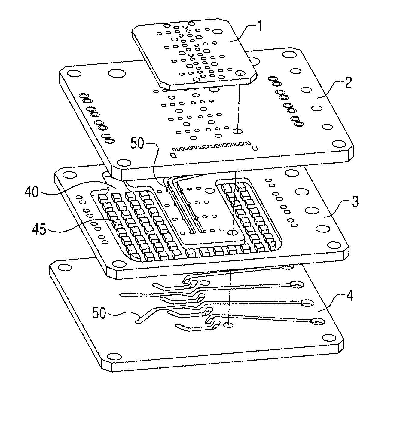
[0010]Another aspect of the present invention relates to a method, comprising stacking a plurality of printed circuit board layers on top of each other in a particular order, wherein one or more of the plurality of printed circuit board layers comprise features associated with: one or more air or fluid channels, one or more inlet or outlet ports, and one or more electrical circuits. The

Problems solved by technology

Some manufacturers may also offer stacked acrylic ported manifolds but lack the associated electronic circuitry and are expensive to produce.

Method used


Image

  • Devices with pneumatic, hydraulic and electrical components
  • Devices with pneumatic, hydraulic and electrical components
  • Devices with pneumatic, hydraulic and electrical components

Examples


Embodiment Construction

[0039]In the following description, for purposes of explanation and not limitation, details and descriptions are set forth in order to provide a thorough understanding of the present invention. However, it will be apparent to those skilled in the art that the present invention may be practiced in other embodiments that depart from these details and descriptions.

[0040]Additionally, the word “exemplary” is used throughout this description to mean serving as an example, instance, or illustration. Any embodiment or design described herein as “exemplary” is not necessarily to be construed as preferred or advantageous over other embodiments or designs. Rather, use of the word exemplary is intended to present concepts in a concrete manner. It should be also noted that the term “manifold” is sometimes used in this specification to refer in general to a system of moving fluids or gases is a junction of pipes or channels, typically bringing one into many or many into one.

[0041]As noted earlie...


PUM

PropertyMeasurementUnit
Flow rateaaaaaaaaaa

Abstract

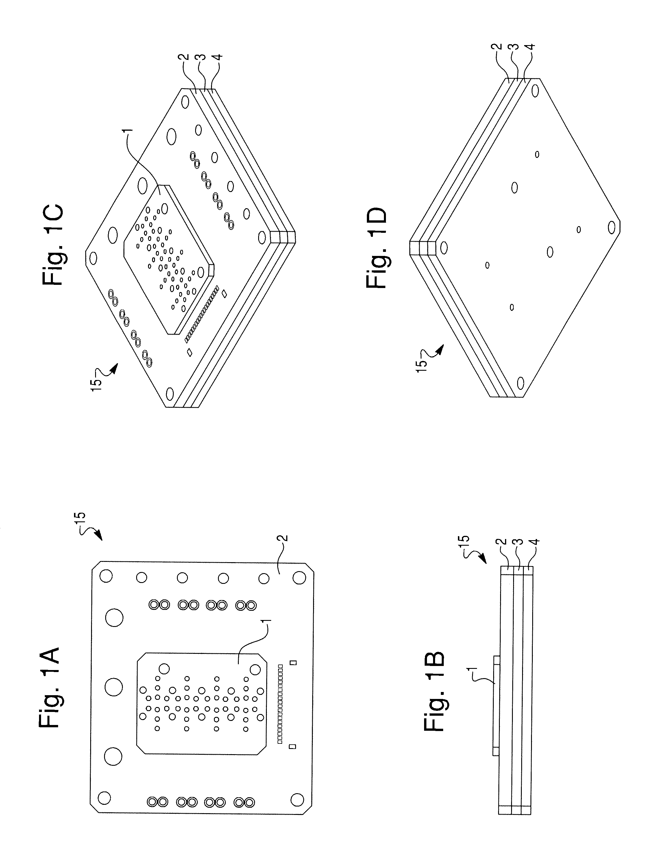
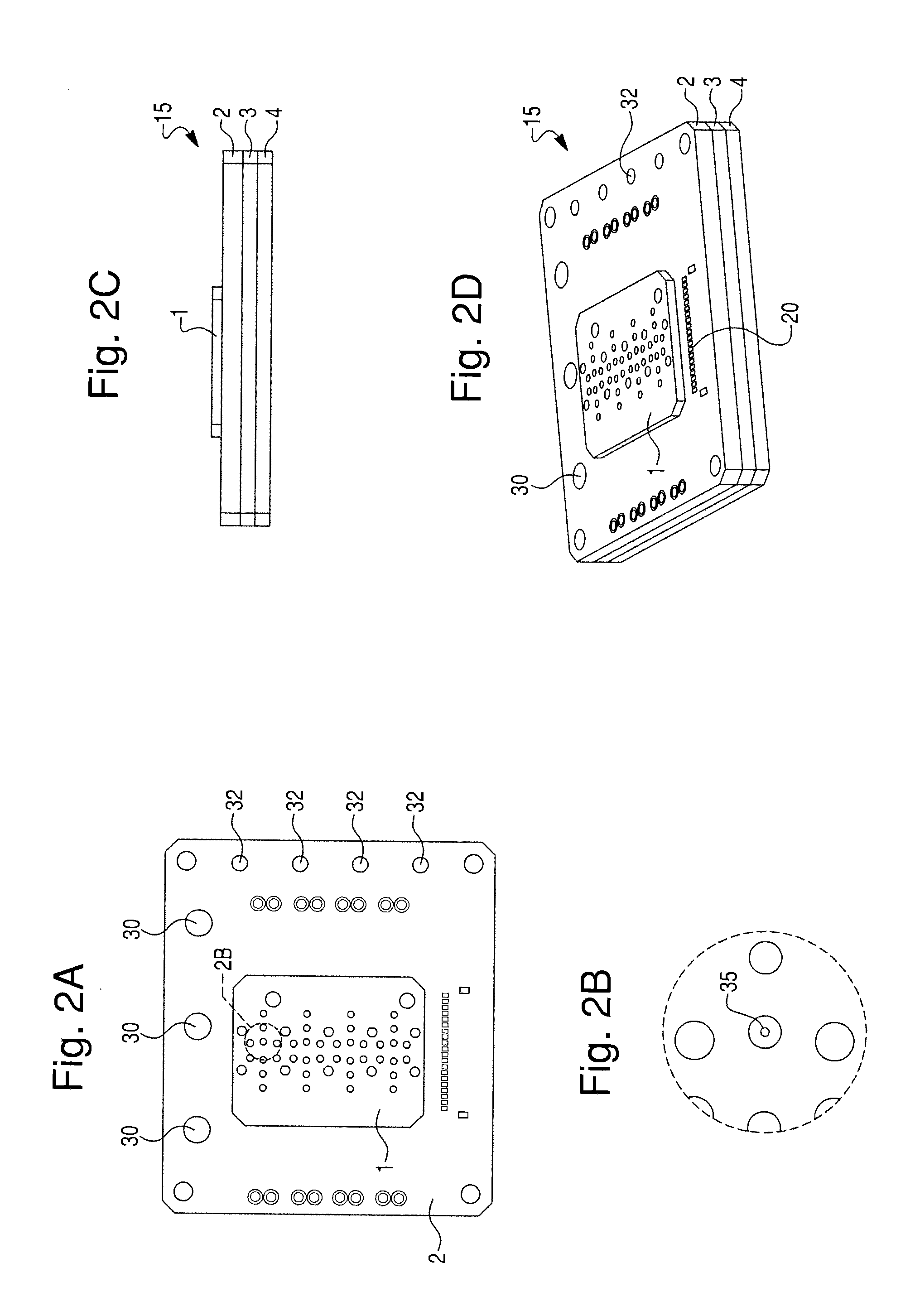
Method and devices are provided that integrate various internal channels and inlet and outlet ports, configured to operate with air or fluidics, with electrical circuitry. The devices comprise internal channels and outlet / inlet ports that are integrated into multiple layers of printed circuit boards. A multi-layer printed circuit board assembly is produced by laminating the plurality of layers together. The multi-layer printed circuit board assembly can accommodate a variety of off-the-shelf components, as well as electrical circuits and electronic components.

Description

CROSS-REFERENCE TO RELATED PATENT APPLICATIONS[0001]This instant application claims priority to and benefit of U.S. Provisional Application 61 / 314,950 filed Mar. 17, 2010, the disclosure of which is incorporated by reference herein in its entirety.FIELD OF INVENTION[0002]The present invention relates generally to the field of printed circuit boards and devices with air / fluidic channels. More particularly, the present invention relates to manufacturing devices with integrated air and / or fluidic channels and electronic circuitry.BACKGROUND OF THE INVENTION[0003]This section is intended to provide a background or context to the invention that is recited in the claims. The description herein may include concepts that could be pursued, but are not necessarily ones that have been previously conceived or pursued. Therefore, unless otherwise indicated herein, what is described in this section is not prior art to the description and claims in this application and is not admitted to be prior ...

Claims


Application Information

Patent Timeline
IPC IPC(8): H05K1/00H01B7/00H05K3/36
CPCH05K1/0272H05K1/185Y10T29/49126H05K2201/041H05K2203/162H05K3/4611
Inventor EMERY, KEITH E. G.JONES, THOMAS
Owner DELTA DESIGN
Learn More