Extremity imaging apparatus for cone beam computed tomography

a computed tomography and extremity imaging technology, applied in the field of diagnostic imaging, can solve the problems of difficult to obtain cbct, hampered cbct imaging of legs, arms, other extremities, etc., and achieve the effect of achieving a much more than about 180 degree revolution for knee or other imaging

Active Publication Date: 2011-09-22
CARESTREAM HEALTH INC +1
View PDF6 Cites 62 Cited by
  • Summary
  • Abstract
  • Description
  • Claims
  • Application Information

AI Technical Summary

Benefits of technology

[0020]It is an advantage of the present invention that it allows imaging of foot and ankle extremities for a patient who is standing or sitting.
[0021]According to one aspect of the present invention there is provided an apparatus for cone beam computed tomography of a portion of a lower leg of a patient, the apparatus comprising: a radiation source; a radiation source transport actuable to move the source along at least a portion of an arcuate source path within a housing, wherein the source path extends from one side of a circumferential gap in the housing to the other side of the circumferential gap and has a radius R2 about a center; a pedestal indent on the housing for placement of the patient's foot; a digital radiation detector; a detector transport actuable to move the detector along at least a portion of an arcuate detector path within the housing, the detector path having a radius R1 about the center and concentric with the source path, wherein R1 is less than R2, and wherein the detector path extends from one side of the pedestal indent to the other; and a gap closure apparatus that is movable to a position that continues the detector path across the circumferential gap and that encloses the detector path.

Problems solved by technology

Although 3-D images of diagnostic quality can be generated using CBCT systems and technology, a number of technical challenges remain.
CBCT Imaging of legs, arms, and other extremities can be hampered by physical obstruction from a paired extremity.
This is an obstacle that is encountered in obtaining CBCT image projections for the human leg or knee, for example.
However, in some cases it can be difficult to obtain much more than about 180 degree revolution for imaging the knee or other joints and other applications.
This arrangement can be particularly disadvantageous for a number of reasons.
Another problem with conventional approaches relates to imaging of a load-bearing extremity such as the human leg.
However, it can be readily appreciated that while this type of simulation allows some approximation of load-bearing limb response, it can be inaccurate.
Another difficulty with the Sukovic et al.
'888 apparatus and with other devices require, not only noticeably compromises image quality, but also places the patient too near the radiation source, so that radiation levels are considerably higher.
With the C-shaped gantry arrangement shown, centering the subject at the center of rotation of source and detector would apply considerably higher radiation amounts with each projection and severely compromise image quality.
Any other positioning of the subject, such as closer to the detector, might reduce radiation levels over some part of the image capture sequence, but would result in unduly complex image reconstruction problems, since this would actually vary the distances between radiation source and subject and between subject and detector with each projection image obtained.
It can be appreciated that this requirement is unreasonable or impossible for many situations in which an injured knee is being imaged.
Thus, the C-shaped gantry shown would not be suitable for imaging only one knee of the patient.
The solution described would irradiate both knees, increasing the amount of tissue exposed to radiation and reducing image quality.
Imaging of the foot and ankle presents additional obstacles for CBCT projection image capture.
The shape of the foot itself makes it difficult to provide a suitable path for the x-ray source and detector for obtaining a set of projection images that can be used for accurate 3-D reconstruction.
'888 disclosure, centering the foot between source and detector, suffer from the same problems of poorly positioned exposure and noticeably compromised image quality.
This type of conventional solution suffers from reduced image quality and increases the amount of patient anatomy that receives radiation.
It can be seen that although a number of solutions have been proposed to address the problem of CBCT extremity imaging, conventional solutions fall short of what is needed with regard to both usability and performance.

Method used


Image

  • Extremity imaging apparatus for cone beam computed tomography
  • Extremity imaging apparatus for cone beam computed tomography
  • Extremity imaging apparatus for cone beam computed tomography

Examples


Embodiment Construction

[0063]The following is a detailed description of the preferred embodiments of the invention, reference being made to the drawings in which the same reference numerals identify the same elements of structure in each of the several figures.

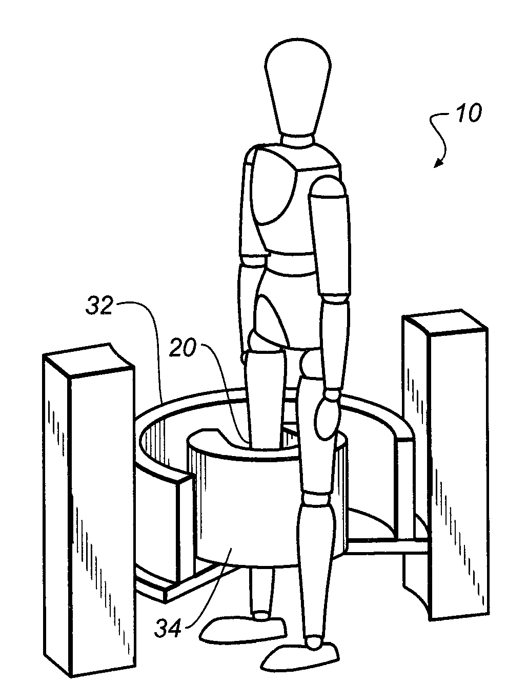
[0064]In extremity imaging, particularly for imaging the lower paired extremities, improvements are needed, including the following:[0065](i) improved placement of the radiation source and detector to provide acceptable radiation levels and image quality throughout the scanning sequence;[0066](ii) system flexibility for imaging at different heights with respect to the rotational axis of the source and detector, including the flexibility to allow imaging with the patient standing or seated comfortably, such as with a foot in an elevated position, for example;[0067](iii) improved patient accessibility, so that the patient does not need to contort, twist, or unduly stress limbs or joints that may have been injured in order to provide images of those bo...


PUM


Abstract

An apparatus for cone beam computed tomography of lower leg portions of a patient has a radiation source and a source transport actuable to move the source along an arcuate source path within a housing, from one side of a circumferential gap to the other and has a radius R2 about a center. A housing is provided for placement of the patient's foot. A digital radiation detector has a detector transport actuable to move the detector along an arcuate detector path within the housing, the detector path having a radius R1 about the center and concentric with the source path, wherein R1 is less than R2, and wherein the detector path extends from one side of the pedestal indent to the other. A gap closure apparatus is movable to a position that continues the detector path across the circumferential gap and encloses the detector path.

Description

CROSS REFERENCE TO RELATED APPLICATIONS[0001]This application claims priority to U.S. Ser. No. 61 / 322,516, provisionally filed on Apr. 9, 2010, entitled “Cone Beam CT Apparatus for Medical Imaging”, to Yorkston et al.[0002]This application claims priority to U.S. Ser. No. 61 / 422,679, provisionally filed on Dec. 14, 2010, entitled “EXTREMITY IMAGING APPARATUS FOR CONE BEAM COMPUTED TOMOGRAPHY”, to Yorkston et al.[0003]This is a Continuation-in-Part of U.S. Ser. No. 12 / 771,250, filed on Apr. 30, 2010, entitled “EXTREMITY IMAGING APPARATUS FOR CONE BEAM COMPUTED TOMOGRAPHY” to Yorkston et al., which claims priority to U.S. Ser. No. 61 / 175,091 provisionally filed on May 4, 2009, entitled “Cone Beam Computed Tomography (CBCT) For Extremity Imaging”.[0004]These references are incorporated herein by reference.FIELD OF THE INVENTION[0005]The invention relates generally to diagnostic imaging and in particular to cone beam imaging systems used for obtaining volume images of extremities.BACKGR...

Claims


Application Information

Patent Timeline
Patent Type & Authority Applications(United States)
IPC IPC(8): A61B6/03
CPCA61B6/032A61B6/04A61B6/4291A61B6/466A61B6/505A61B6/4085A61B6/4405A61B6/4441A61B6/4447
Inventor YORKSTON, JOHNSNYDER, WILLIAM F.SIEWERDSEN, JEFFREY H.
Owner CARESTREAM HEALTH INC
Why Eureka
Try Eureka