
High bandwidth connector

Active Publication Date: 2011-09-22
AMPHENOL CORP
View PDF10 Cites 108 Cited by
  • Summary
  • Abstract
  • Description
  • Claims
  • Application Information

AI Technical Summary

Benefits of technology

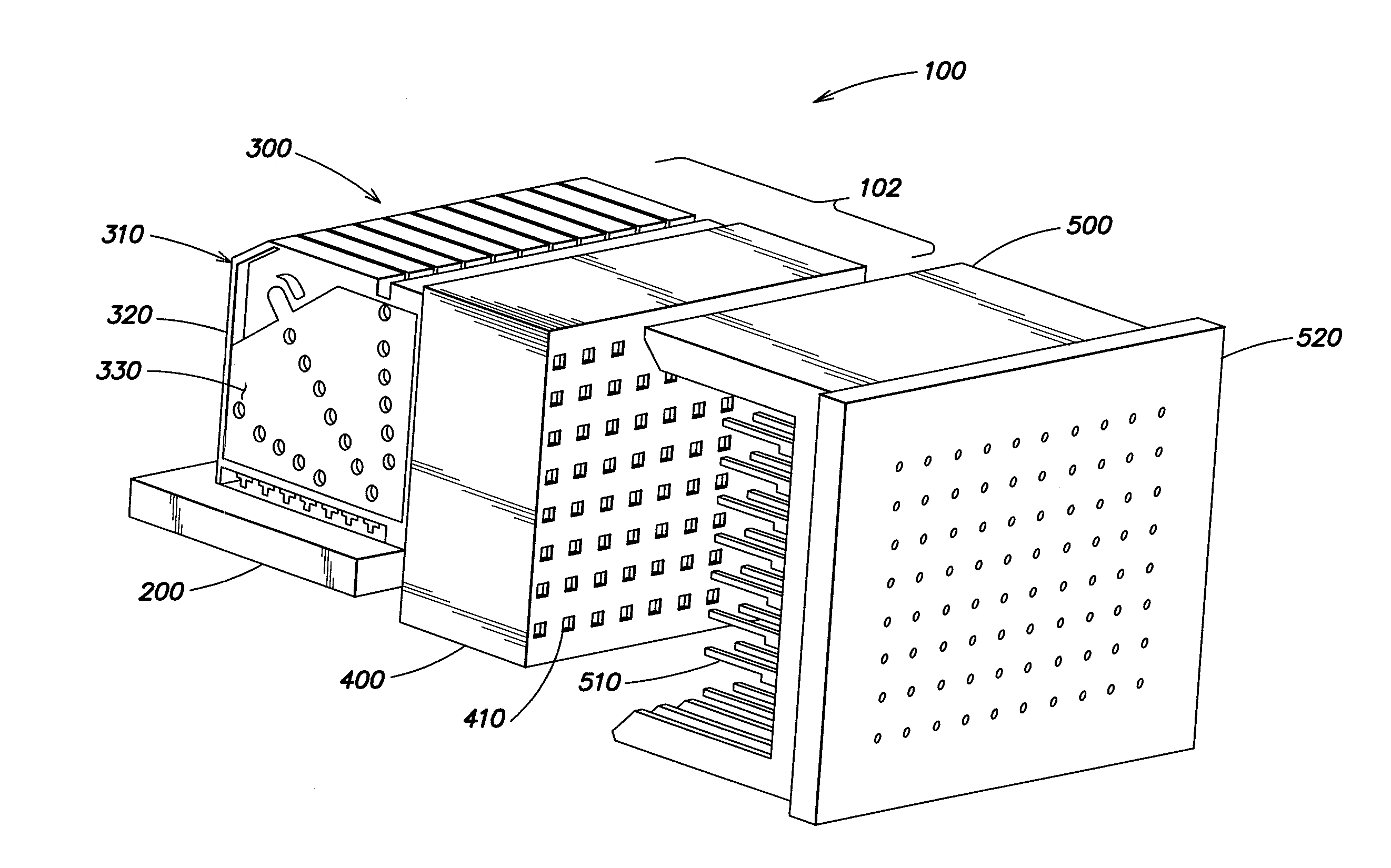
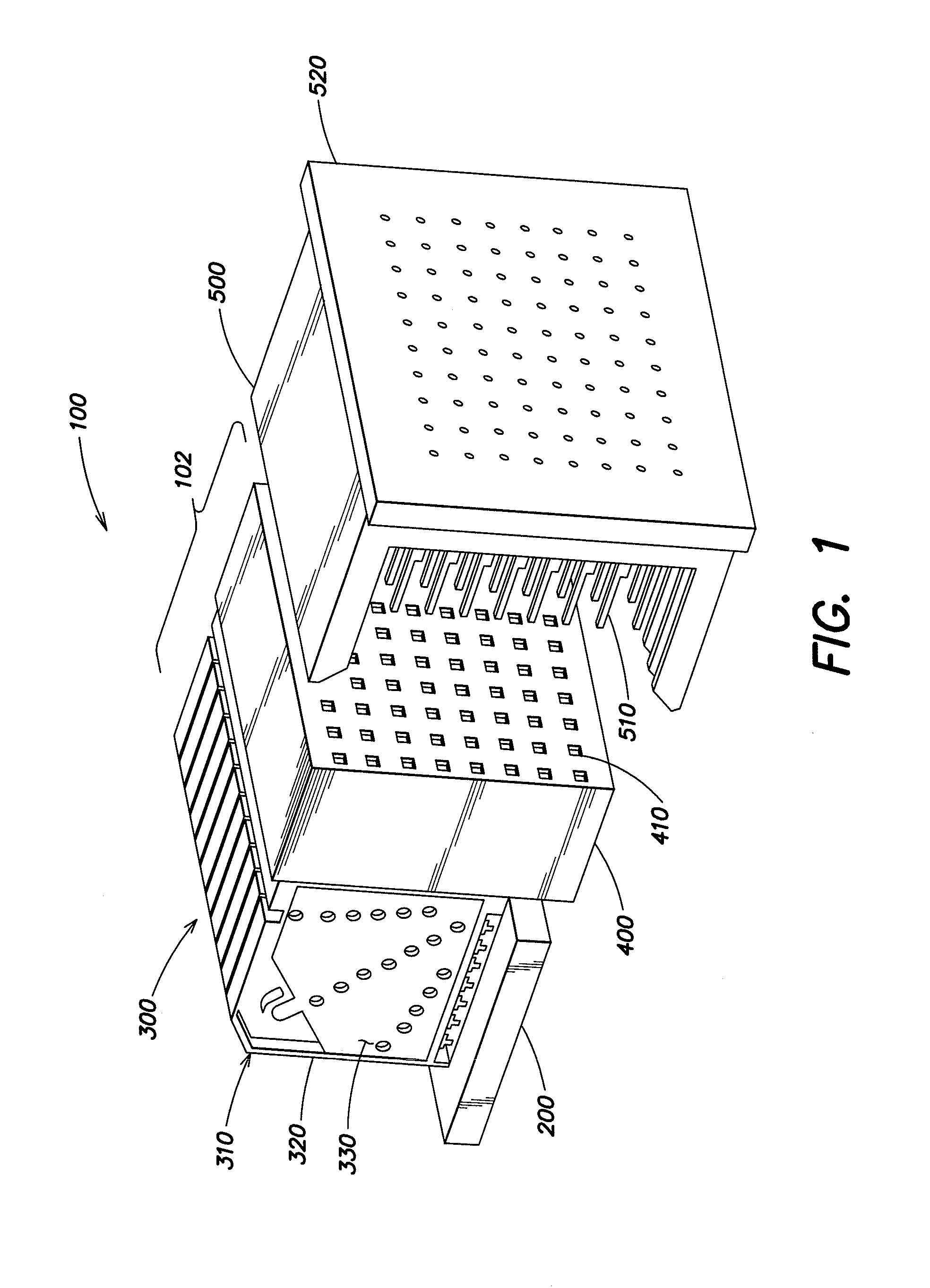
[0011]An improved open pin field connector may be provided through a combination of one more design techniques. These techniques may provide suitable values of properties such as cross talk, impedance and / or insertion loss, regardless of which conductive elements in the connector are used to carry high speed signals and which are used as ground conductors or to carry low speed signals.
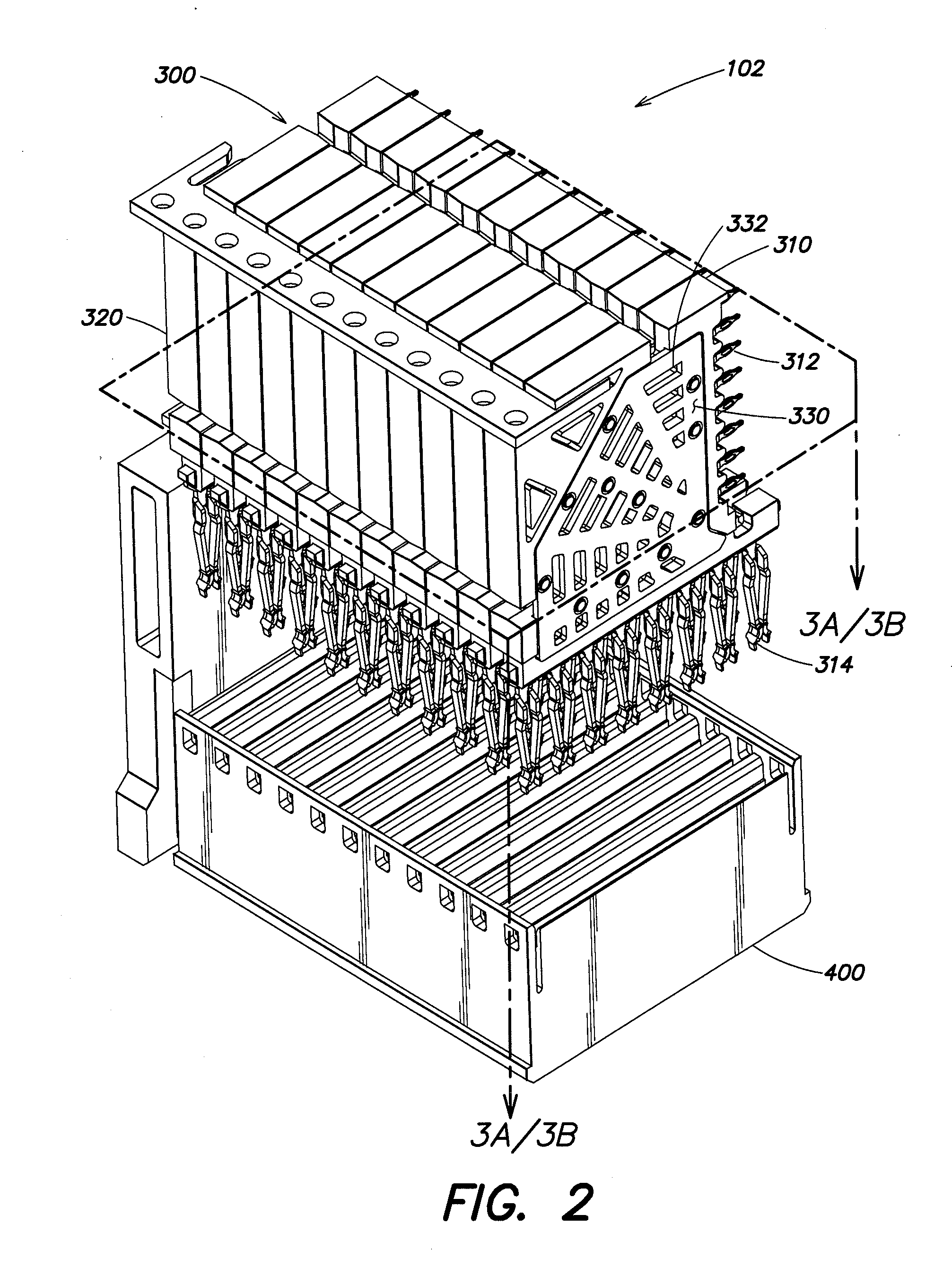
[0013]Various placements of lossy material in the electrical connector, such as adjacent to conductive elements, are suitable. In some embodiments, the lossy material may also be used to fill regions between conductive elements. The positioning of the lossy material relative to conductive elements may be selected to reduce resonance in pairs of conductive elements if used as grounds without causing an unacceptable decrease in signal conductive elements used to carry signals.

Problems solved by technology

Though, it can frequently be a challenge in designing an electrical connector to provide a suitable number of signal paths in a relatively confined area in which all of the signal paths have electrical properties that support a desired level of performance for an overall electronic system.
Such a technique may employ lossy material that is a lossy conductor.

Method used


Image

  • High bandwidth connector
  • High bandwidth connector
  • High bandwidth connector

Examples


Embodiment Construction

[0061]The inventors have recognized and appreciated that an open pin field connector with desirable electrical and mechanical properties may be achieved through the use of one or more construction techniques.

[0062]These techniques may be used in a suitable combination that may simultaneously provide desired impedance, cross talk, insertion loss or other electrical properties for signal paths through a connector. In some embodiments, these techniques may be applied to an open pin field connector such that one or more of these electrical properties may be uniform, to within some tolerance, for any signal conductors within the connector. As a specific example, techniques as described herein may be used to provide an open pin field connector, constructed in accordance with the HM standard, that provides a characteristic impedance with acceptable cross talk and insertion loss over a frequency range that is sufficient to support data rates at 10 Gbps or greater, regardless of which pair o...


PUM


Abstract

An improved open pin field connector is provided for enhanced performance when carrying high speed signals by selective application of one or more techniques for controlling electrical performance parameters. Lossy material may be positioned adjacent to conductive elements of the connector so as to reduce resonance in pairs of conductive elements and / or to provide a desired characteristic impedance for pairs of differential signal conductors. The lossy material may be shaped and positioned to avoid capacitive coupling that might otherwise increase cross talk. In a right angle connector, the lossy material may have a step-wise increase in thickness to provide comparable loss along longer and shorter conductive elements. Conductive elements may be shaped to balance performance characteristics of pairs selected to carry differential signals regardless of orientation along a row or column. Alternatively, conductive elements may have narrowed regions, covered with lossy portions, for reducing resonance while supporting DC signal propagation.

Description

RELATED APPLICATION[0001]This application claims the benefit of U.S. Provisional Patent Application Ser. No. 61 / 307,824, filed Feb. 24, 2010, entitled “High Bandwidth Connector,” by Gailus et al., which is hereby incorporated by reference in its entirety.BACKGROUND OF INVENTION[0002]1. Field[0003]Aspects described relate generally to electrical interconnection systems and more specifically to improved signal integrity in interconnection systems.[0004]2. Discussion of Related Art[0005]In various electrical interconnection systems, separable multi-pin connectors are commonly used. Single-ended and differential pair electrical paths that carry signals in the 1 to 20 Gigabit per second range are provided by signal carrying structures such as cables or integrated circuit packages. Such electrical paths are often present between circuit boards, such as a daughter card and a backplane. Accordingly, separable connectors that carry signals at frequencies in this range are known. Though, it c...

Claims


Application Information

Patent Timeline
Patent Type & Authority Applications(United States)
IPC IPC(8): H01R13/6581
CPCH01R12/724H01R13/514H01R12/737H01R13/6477H01R13/6598H01R13/6474
Inventor ATKINSON, PRESCOTT B.GAILUS, MARK W.HANRAHAN, MARK G.
Owner AMPHENOL CORP
Learn More