Compression device used in ultrasonic measurement, compression control method thereof, and photoacoustic measurement apparatus and control method thereof

a compression control and ultrasonic measurement technology, applied in ultrasonic/sonic/infrasonic diagnostics, applications, diagnostic recording/measuring, etc., can solve problems such as large amount of time and trouble to insert the subject deeply, leakage or overflow of matching liquid, etc., to achieve the effect of suppressing leakage or overflowing of matching liquid

Inactive Publication Date: 2011-09-22
CANON KK
View PDF8 Cites 15 Cited by
  • Summary
  • Abstract
  • Description
  • Claims
  • Application Information

AI Technical Summary

Benefits of technology

[0020]The present invention was made in view of the above problems, and an object of the invention is to provide, as a compression device for compressing a subject that is used in ultrasonic measurement that receives ultrasonic waves from the subject to acquire biological information of the subject, a compression device used in ultrasonic measurement that can match an acoustic impedance with a subject and can suppress leaking or overflowing of a matching liquid, as well as a compression control method thereof, and a photoacoustic measurement apparatus and a control method thereof.
[0021]Another object of present invention is to provide a compression device used in ultrasonic measurement that can make a portion contacted by a person to be examined as well as an acoustic matching medium disposable and can cause a subject to be inserted more deeply and decrease regions that is not measured, as well as a compression control method thereof, and a photoacoustic measurement apparatus and a control method thereof.
[0028]According to the present invention it is possible to realize, as a compression device for compressing a subject that is used in ultrasonic measurement that receives ultrasonic waves from the subject to acquire biological information of the subject, a compression device used in ultrasonic measurement that can match an acoustic impedance with a subject and can suppress leaking or overflowing of a matching liquid, as well as a compression control method thereof, and a photoacoustic measurement apparatus and a control method thereof.
[0029]Further, it is possible to realize a compression device used in ultrasonic measurement that can make a portion contacted by a person to be examined as well as an acoustic matching medium disposable and can cause a subject to be inserted more deeply and decrease regions that can not be measured, as well as a compression control method thereof, and a photoacoustic measurement apparatus and a control method thereof.

Problems solved by technology

However, according to the apparatus discussed in Manohar, et al., gaps are caused due to dead spaces between a part of the subject (breast) and the ultrasound probe in which the part of subject (breast) cannot contact the ultrasound probe.
However, there are the following problems with the conventional example as exemplified by ultrasonic measurement apparatus of Japanese Patent Application Laid-Open No.
Alternatively, when a gel is employed as the matching liquid (acoustic matching medium 906), since the volume thereof changes by the compressing operation there is a risk that the matching liquid (acoustic matching medium 906) will overflow.
However, because the area surrounding the portion to be inserted is covered by the accordion mechanism 905 and the like, a large amount of time and trouble is required to insert the subject deeply.

Method used


Image

  • Compression device used in ultrasonic measurement, compression control method thereof, and photoacoustic measurement apparatus and control method thereof
  • Compression device used in ultrasonic measurement, compression control method thereof, and photoacoustic measurement apparatus and control method thereof
  • Compression device used in ultrasonic measurement, compression control method thereof, and photoacoustic measurement apparatus and control method thereof

Examples


embodiment 1

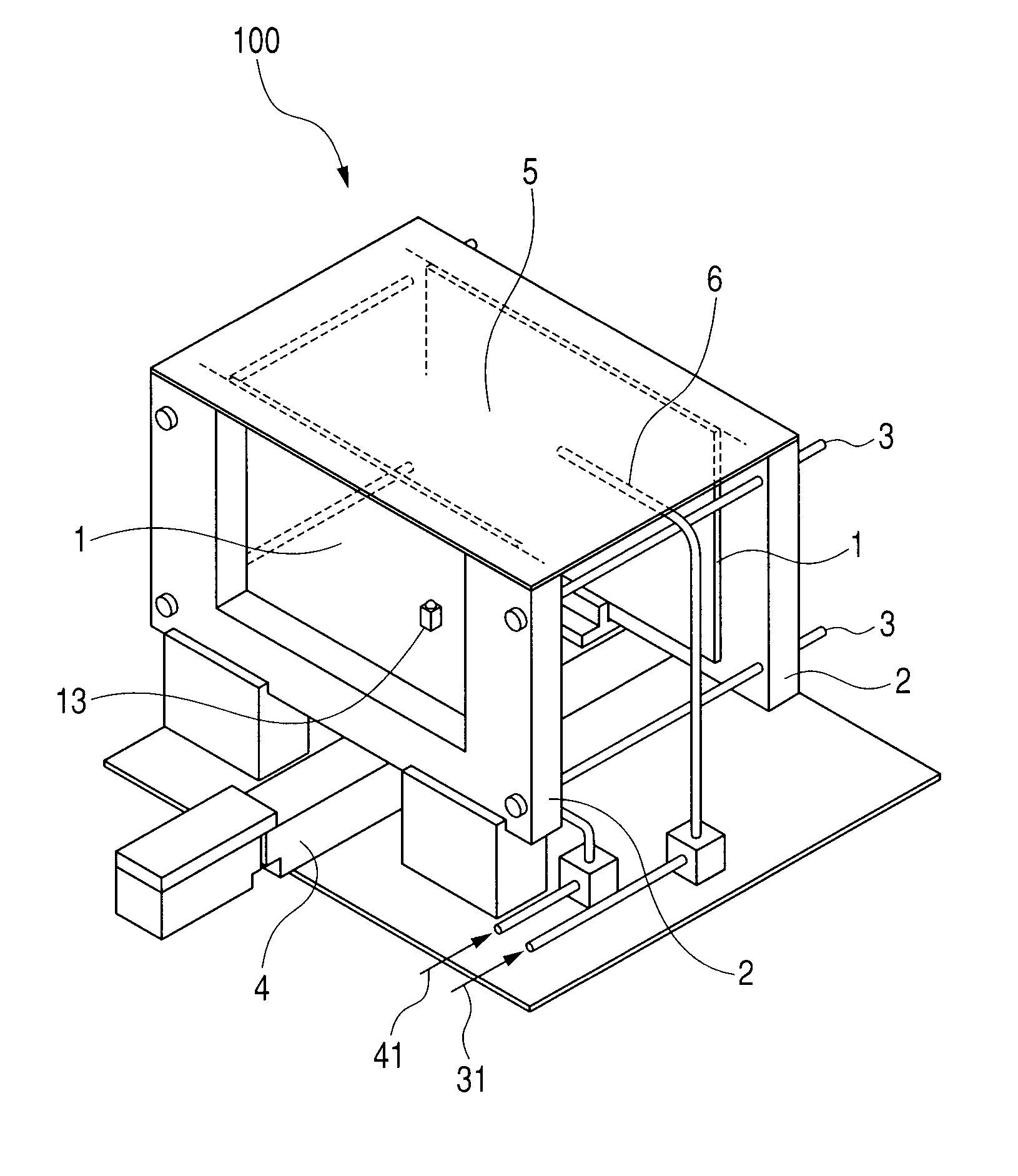
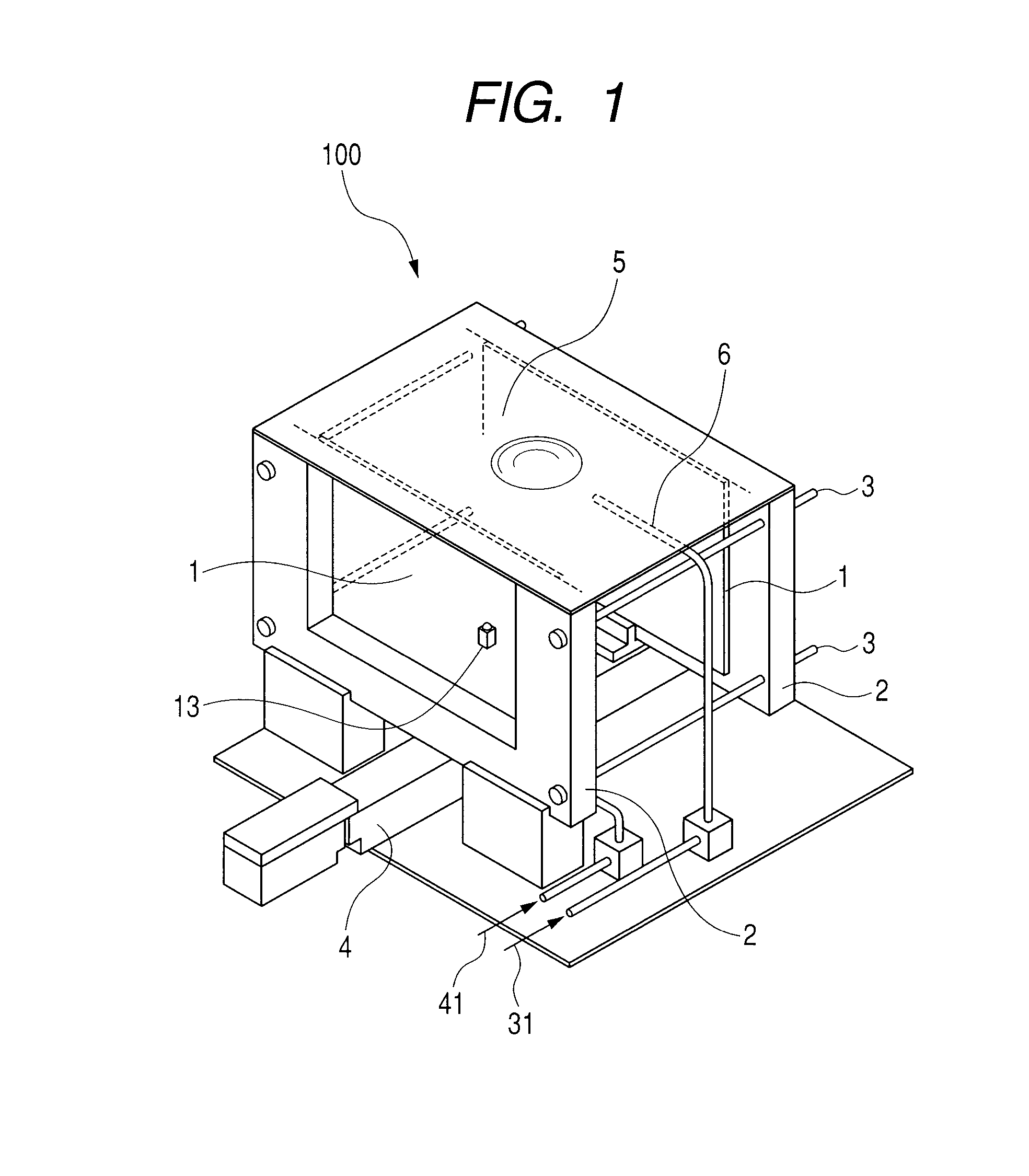
[0050]According to Embodiment 1, a configuration example of a compression device that applies the present invention is described. FIG. 1 illustrates a view that describes the configuration of a compression device according to the present embodiment.

[0051]The configuration illustrated in FIG. 1 includes compression plates 1, compression plate fastening portions 2, guides 3, a compression mechanism 4, and a sheet for setting a subject on 5. Arrows 31 and 41 indicate directions in which matching liquid and lubricant are introduced into the apparatus, respectively.

[0052]The configuration illustrated in FIG. 1 also includes a matching liquid supply line 6, a lubricant supply nozzle 13, and a compression device 100.

[0053]In the compression device 100 of this embodiment, the compression plates 1 for sandwiching a subject are composed of two flat plates that face each other in a vertical direction with respect to a horizontal plane. The two flat plates can be composed of parallel flat plate...

embodiment 2

[0093]In Embodiment 2, a configuration example of a compression device which is provided with a sheet that has a flat central part, and that does not have a concave portion in a central part as in Embodiment 1, is described.

[0094]FIG. 4 is a view that describes the configuration of a compression device according to the present embodiment.

[0095]Components in FIG. 4 which are the same as in FIG. 1 that illustrates Embodiment 1 are denoted by the same reference numerals, and a description of those common components is omitted hereunder.

[0096]According to the present embodiment, the sheet 5 has a flat central part and is stretched between the upper ends of two flat plates that face each other in the vertical direction.

[0097]Because costs may increase due to processing of the sheet 5 when a concave portion is provided in the central part of the sheet 5 as in Embodiment 1, according to the present embodiment a sheet 5 in which the central part is also flat is used.

[0098]Next, a process fr...

embodiment 3

[0110]In embodiment 3, a configuration example of a compression device that compresses a subject more deeply into the compression device is described.

[0111]FIG. 7 is a view that describes the configuration of a compression device according to the present embodiment.

[0112]Components in FIG. 7 that are the same as in FIG. 1 that illustrates Embodiment 1 are denoted by the same reference numerals, and a description of those common components is omitted hereunder.

[0113]In the compression device of the present embodiment, an actuator that pulls one end of a sheet downward while sandwiching a subject is provided below two flat plates that face each other in the vertical direction.

[0114]The above described Embodiment 1 and Embodiment 2 are each configured such that a subject is set on the sheet 5 and compressed together with the sheet 5 between the compression plates 1 by the compression mechanism 4. However, in the present embodiment, as described above, an actuator is provided for compre...


PUM


Abstract

A compression device for compressing a subject that is used in ultrasonic measurement that receives ultrasonic waves from the subject to acquire biological information of the subject, comprising: two compression plates that are used when compressing the subject, and that face each other in a vertical direction with respect to a horizontal plane; a flexible sheet for setting a subject on, which is stretched between upper ends of the two compression plates; a compression mechanism that relatively changes a distance between the two compression plates to sandwich and compress the subject that is set on the flexible sheet through the flexible sheet; and a supply unit for supplying a matching liquid onto the flexible sheet. The apparatus can match an acoustic impedance with a subject and can suppress leaking or overflowing of a matching liquid.

Description

TECHNICAL FIELD[0001]The present invention relates to a compression device used in ultrasonic measurement and a compression control method thereof, and a photoacoustic measurement apparatus and a control method thereof.[0002]More particularly, the present invention relates to a compression device used in a photoacoustic measurement apparatus that radiates near infrared rays inside a subject, receives photoacoustic waves generated inside the subject with an ultrasound probe, and displays a tissue image inside the subject.BACKGROUND ART[0003]Srirang Manohar, et al., The Twente photoacoustic mammoscope: system overview and performance, Physics in Medicine and Biology 50 (2005) 2543-2557 discusses a photoacoustic measurement apparatus that has been developed for use in breast cancer examination.[0004]According to Manohar, et al., a subject (breast) is compressed between a glass plate and an ultrasound probe, and illumination light (near infrared rays) that employs an Nd:YAG laser as a l...

Claims


Application Information

Patent Timeline
Patent Type & Authority Applications(United States)
IPC IPC(8): A61B8/00A61B6/00
CPCA61B5/0091A61B5/0095A61B5/4312A61B5/702A61B2019/205A61B8/406A61B8/4281A61B19/203A61B8/40A61B90/14A61B90/17
Inventor TOKITA, TOSHINOBUNAKAGAWA, KATSUMI
Owner CANON KK
Why Eureka
Try Eureka