
Electrode Delivery System

a delivery system and electrode technology, applied in the field of defibrillator and defibrillation electrodes, can solve the problems of reducing the transmission rate of moisture vapor of electrodes, reducing the ability of defibrillators (or other medical devices) to adhere to patients, and demonstrating excessive contact impedance, etc., to achieve the effect of reducing the moisture vapor transmission ra

Active Publication Date: 2011-09-22
KPR U S LLC
View PDF6 Cites 11 Cited by
  • Summary
  • Abstract
  • Description
  • Claims
  • Application Information

AI Technical Summary

Benefits of technology

[0011]According to an aspect of the present disclosure, an automatic external defibrillator configured to deliver electrical pulses and / or shocks to a heart of a patient during a cardiac emergency is provided and includes a housing supporting an electrical connector; a defibrillator electrode delivery system supported on the housing; and a pair of defibrillation electrode pads supported by the defibrillator electrode delivery system. Each of the pair of defibrillation electrode pads is pre-connected to the electrical connector of the housing. A hydrogel layer of each defibrillation electrode pad is retained by the defibrillator electrode delivery system in such a manner so as to reduce a moisture vapor transmission rate thereof.
[0028]According to another aspect of the present disclosure, an automatic external defibrillator configured to deliver electrical pulses and / or shocks to a heart of a patient during a cardiac emergency is provided and includes a housing supporting an electrical connector, a battery and high voltage circuitry; and a pair of defibrillation electrode pads supported on the housing, wherein each of the pair of defibrillation electrode pads is pre-connected to the electrical connector of the housing, and wherein each defibrillation electrode pad is in electrical communication with the battery and the high voltage circuitry. The defibrillator is automatically activated by a separation of at least one of the pair of defibrillation electrode pads from the housing. A hydrogel layer of each defibrillation electrode pad is retained by the housing in such a manner so as to reduce a moisture vapor transmission rate thereof.

Problems solved by technology

When the conductive gel becomes too dry, it may lose its ability to adhere to a patient or demonstrate excessively high contact impedance.
Compatibility among defibrillators (or other medical devices) and electrodes of different brands is often lacking, which can cause confusion as to which particular electrode to use with a given defibrillator.
As can be appreciated, testing electrodes in this fashion leads to waste, as the electrodes that are not compatible are likely to become too thy if not used in a timely fashion.

Method used


Image

  • Electrode Delivery System
  • Electrode Delivery System
  • Electrode Delivery System

Examples


Embodiment Construction

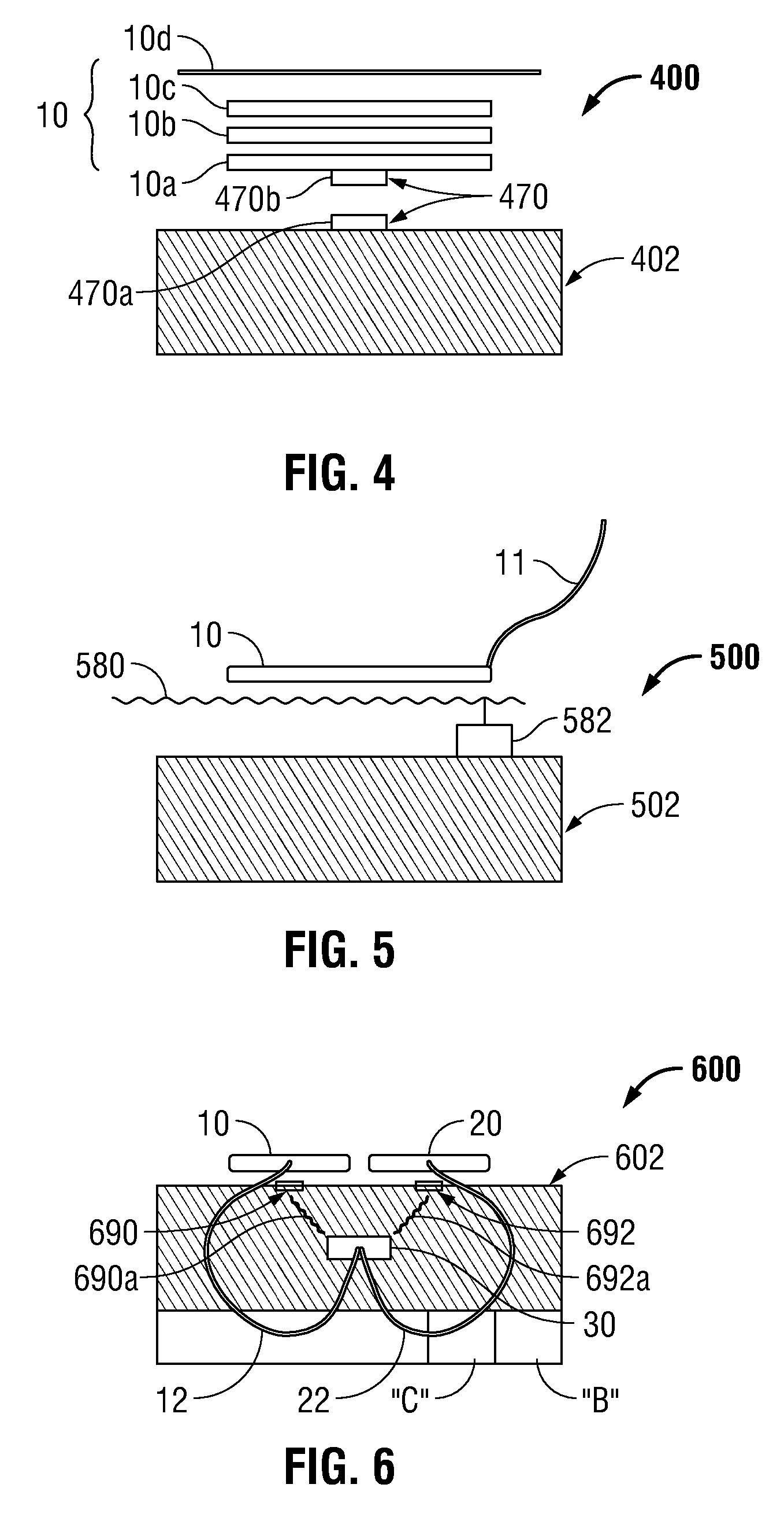
[0043]Embodiments of the presently disclosed defibrillator electrode delivery system will now be described in detail with reference to the drawing figures wherein like reference numerals identify similar or identical elements.

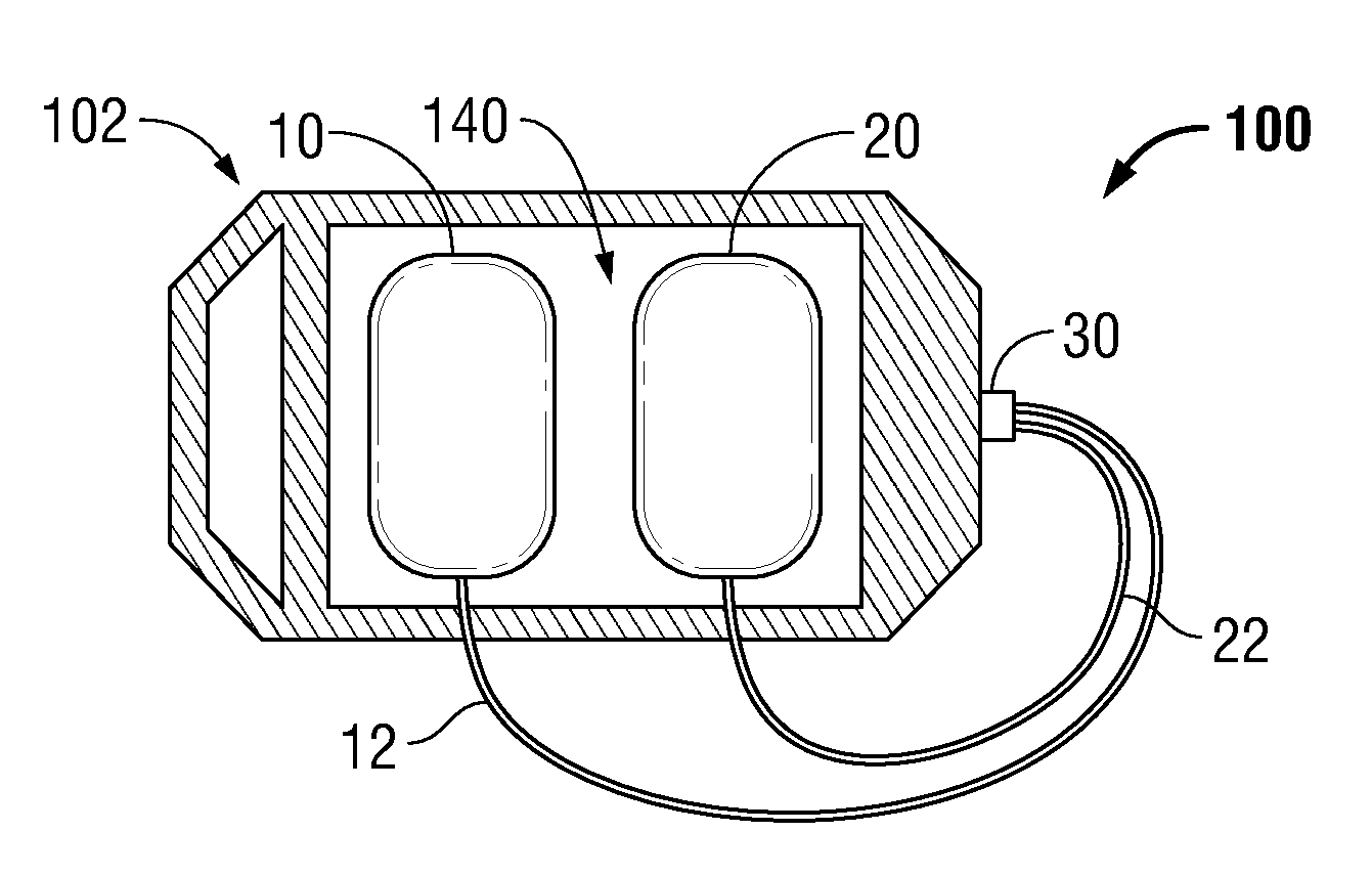
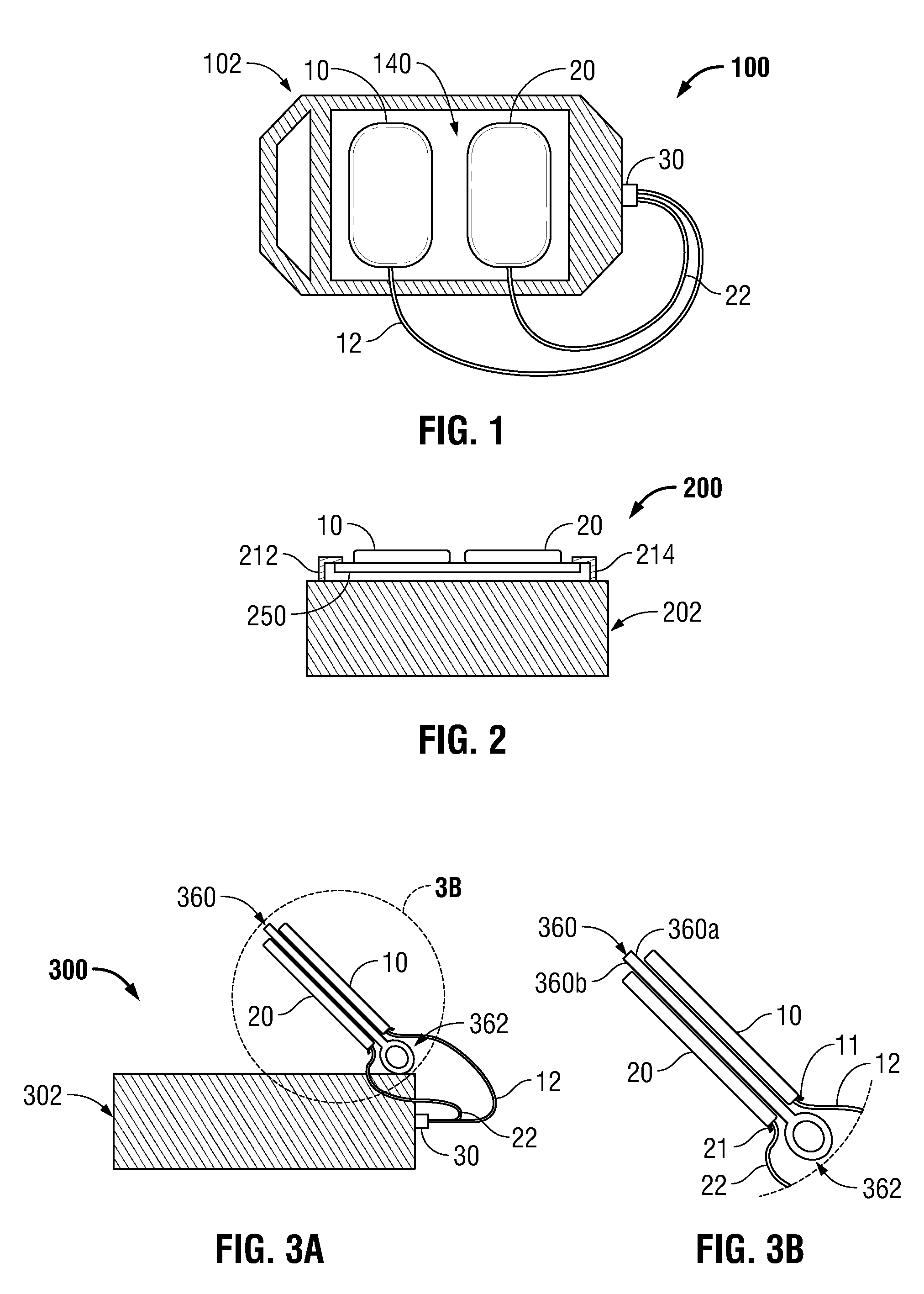
[0044]As illustrated in FIG. 1, a defibrillator electrode delivery system, according to an embodiment of the present disclosure, is generally designated as 100. Defibrillator electrode delivery system 100 includes an automatic external defibrillator (AED) 102 defining a surface 140 configured to store or retain a pair of electrode pads 10, 20. Electrode pads 10, 20 are electrically connectable to or pre-connected to AED 102 via respective lead wires 12, 22 joined at a connector 30.

[0045]Surface 140 is coated with a release material to selectively adhere electrode pads 10, 20 thereto and to facilitate the removal of electrode pads 10, 20 therefrom when needed. For example, the release material may be Teflon, silicone, and combinations thereof.

[0046]In this confi...


PUM


Abstract

According to an aspect of the present disclosure, an automatic external defibrillator configured to deliver electrical pulses and / or shocks to a heart of a patient during a cardiac emergency is provided and includes a housing supporting an electrical connector; a defibrillator electrode delivery system supported on the housing; and a pair of defibrillation electrode pads supported by the defibrillator electrode delivery system. Each of the pair of defibrillation electrode pads is pre-connected to the electrical connector of the housing. A hydrogel layer of each defibrillation electrode pad is retained by the defibrillator electrode delivery system in such a manner so as to reduce a moisture vapor transmission rate thereof.

Description

CROSS-REFERENCE TO RELATED APPLICATIONS[0001]The present application claims the benefit of and priority to U.S. Provisional Application Ser. No. 61 / 315,159, filed on Mar. 18, 2010, entitled “Electrode Delivery System,” the entire content of which is being incorporated herein by reference.BACKGROUND[0002]1. Technical Description[0003]The present disclosure relates to defibrillator and defibrillation electrodes and, more particularly, to systems, methods and packages to facilitate the use and connection of defibrillation electrodes to a defibrillator prior to the electrodes being used on a patient, while allowing the electrodes to maintain a sufficient amount of moisture to be able to properly function.[0004]2. Background of Related Art[0005]Electrodes which are typically used in medical applications generally include a conductor and a connector. The connector is attached at one end to the conductor and includes a plug at the other end to be plugged into a defibrillator or other devic...

Claims


Application Information

Patent Timeline
Patent Type & Authority Applications(United States)
IPC IPC(8): A61N1/18
CPCA61B19/026A61B2562/125A61N1/3993A61N1/3925A61N1/3968A61N1/046A61B50/30
Inventor COPP-HOWLAND, WARRENGARSTKA, ERICKSELVITELLI, DAVIDTREMBLAY, KATHLEENGASIORSKI, CAROLINE
Owner KPR U S LLC
Learn More