Stent device having focal elevating elements for minimal surface area contact with lumen walls

a technology of stent and lumen wall, which is applied in the field of stent devices, can solve the problems of accumulated blockage of stent, inability to perform the intended function, and inability to reduce the pressure burden, so as to reduce the contact area, minimize the surface contact, and reduce the effect of pressure burden

a technology of stent and lumen wall, which is applied in the field of stent devices, can solve the problems of accumulated blockage of stent, inability to perform the intended function, and inability to reduce the pressure burden, so as to reduce the contact area, minimize the surface contact, and reduce the effect of pressure burden

US20110230954A1Inactive Publication Date: 2011-09-22INTACT VASCULAR

Image

  • Stent device having focal elevating elements for minimal surface area contact with lumen walls
  • Stent device having focal elevating elements for minimal surface area contact with lumen walls
  • Stent device having focal elevating elements for minimal surface area contact with lumen walls

Examples


Embodiment Construction

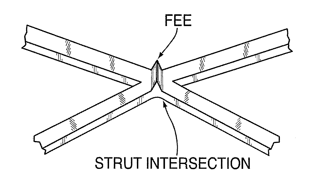
[0044]In the present disclosure, a stent may be improved in design and performance in the human body by the use of focal elevating elements on the outer surface of the device to minimize surface area contact of the stent material with the organ lumen walls. The focal elevating elements operate to elevate adjacent sections (struts) of the stent away from the organ lumen walls to minimize friction generated at contact areas. The focal elevating elements increase outward pressure at contact points with the organ lumen walls to maintain them in stable contact, while elevating the adjacent sections of the stent out of contact with the organ lumen walls. The focal elevating elements (FEEs) are strategically placed to reduce the overall regional friction load (thought to be a source of inflammation, cellular proliferation, and the healing response that leads to re-stenosis) of the area being held open. These elevated contact points of the FEEs are believed to limit the histological respons...


PUM


Abstract

An improved stent device has a body structure in tubular form sized to an organ lumen in which it is to be used and made of a wire mesh or cage structure of interwoven or interdigitated strut sections, and a plurality of focal elevating elements of relatively small point-like size or vector-like edge in an array over outer surfaces of the wire mesh or strut sections of the stent body structure. The focal elevating elements elevate the wire mesh or strut sections away from and minimize surface area contact with the organ lumen walls. They also reduce contact pressure in regions neighboring the focal elevating elements in order to minimize trauma due to contact or movement against the organ lumen walls. A preferred use for the stent device is in a blood vessel lumen, particularly to retain plaque dissection after balloon angioplasty.

Description

[0001]This U.S. Patent Application claims the priority filing date of U.S. Provisional Application 61 / 349,836 filed on May 29, 2010, and is a continuation-in-part of co-pending U.S. patent application 12 / 790,819 filed May 29, 2010, which was a continuation-in-part of co-pending U.S. patent application 12 / 483,193, filed Jun. 11, 2009, of the same inventors.TECHNICAL FIELD[0002]This invention relates to an improved stent device for use in the body, and particularly a stent device that makes minimal surface area contact with lumen walls.BACKGROUND OF INVENTION[0003]A stent may be placed during routine medical practice within a tubular body structure to restore or support its structural integrity. It can provide a structural scaffold within arteries, veins, bile ducts, pancreatic ducts, ureters, trachea, bronchus, ear canal, eye canal, sinuses, intestinal tracts, and other structures. Existing stent designs place an elongated scaffold structure of foreign material in contact with the su...

Claims


Application Information

Patent Timeline
22 Sep 2011
Publication
US20110230954A1
IPC
A61F2/82
CPC
A61F2/848; A61F2/915; A61F2002/91558; A61F2230/0054; A61F2250/0039; A61F2220/0016; A61F2230/0017; A61F2250/0036
Inventors
SCHNEIDER, PETER; GIASOLLI, ROBERT