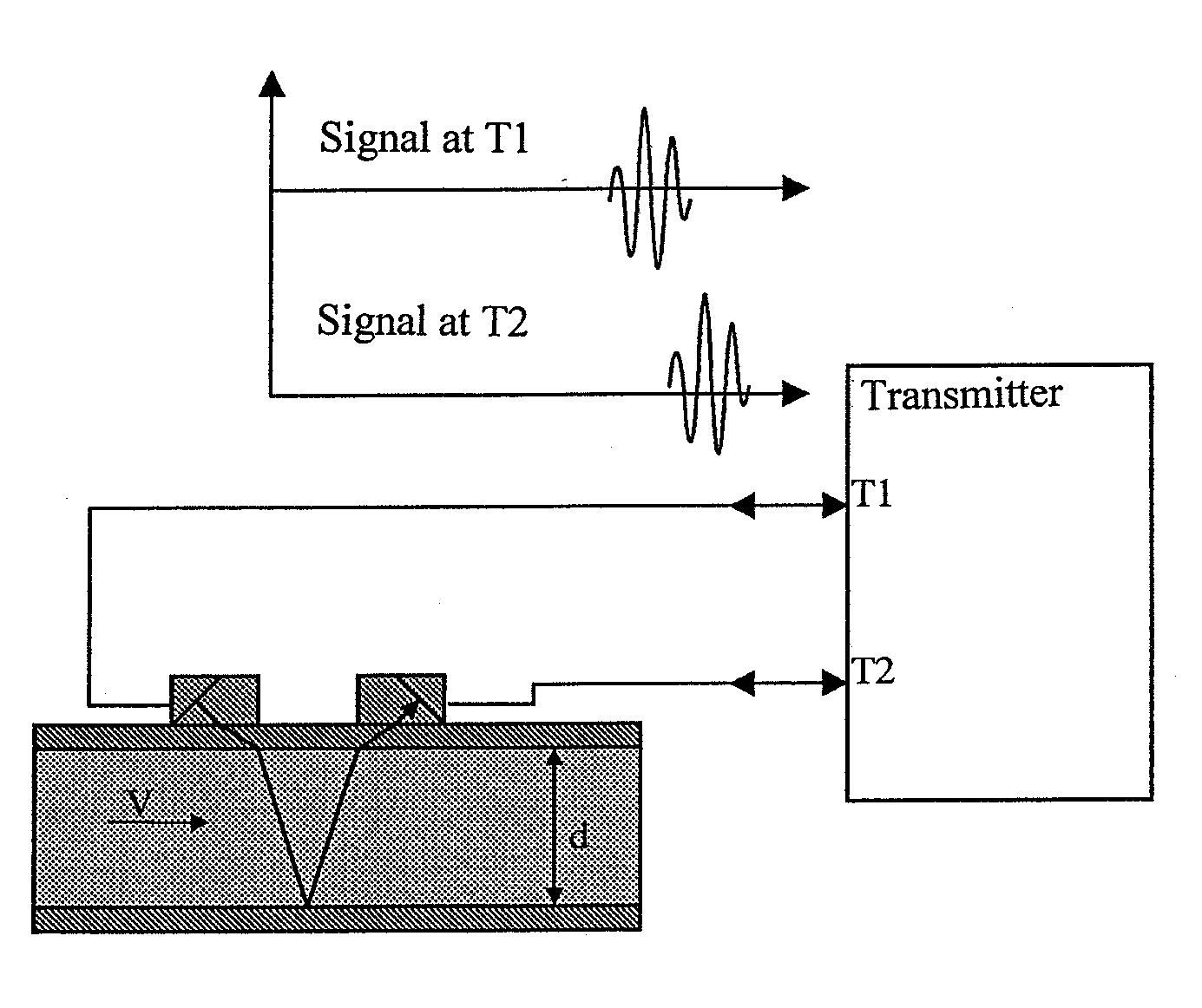
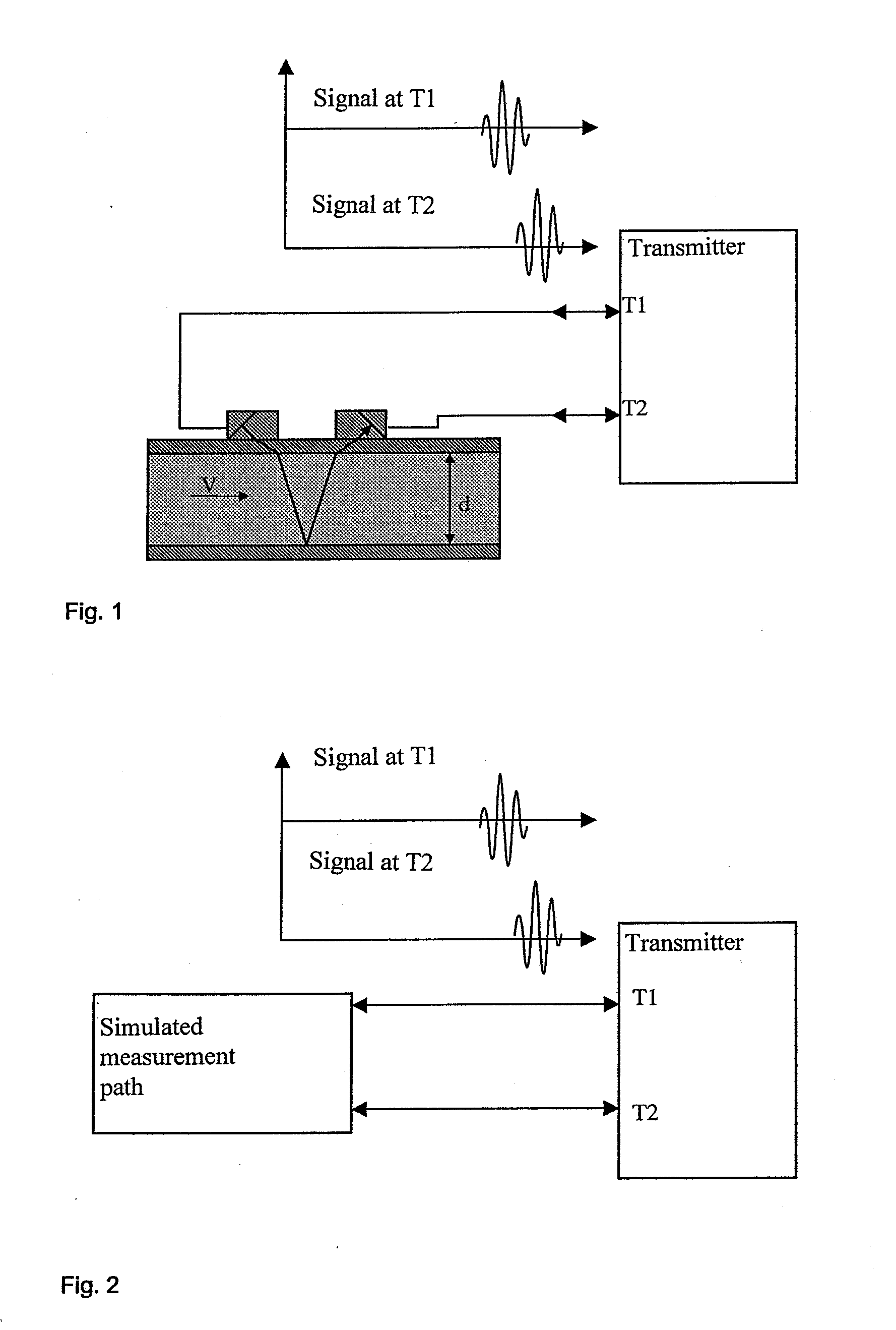
[0013]According to the present invention, this object is achieved by creating an artificial
simulation of the measurement path, which responds to the emitted signals generated by the
transmitter at the two acoustic
transducer terminals with received signals, which are delayed with respect to the emitted signals by a predetermined transit time and whose transit times differ by a predetermined transit time difference. In order to achieve this, the artificial measurement path contains two digital-to-analog
converters, each of which is assigned to a terminal of the transmitter and one of which generates the
signal in the flow direction, and the other generates the signal against the flow direction. This is achieved by storing the digital representations of these two signals in a memory and having the emitted signal of the transmitter start the output of the signals to the two outputs of the digital-to-analog converter. As a result of this method, the transit times of the two signals can be varied continuously without the need for a particularly high
clock rate. The
clock rate of the
clock generator only has to be high enough to conform to the sampling theorem. The transit time difference of the two signals can be simulated with a resolution that is smaller than 1 / 1000 of the clock period of the
clock generator. Any signal shape of the two signals can be specified, meaning that it is possible to simulate the signal shape differences that can be observed at higher flow velocities. The method makes it possible to use commercially available signal generators. This supports and simplifies
authentication of the calibration with respect to national and international standards.
[0019]The method offers the possibility to calibrate the transmitter without the influences of the other components of the measuring apparatus. A correction factor is calculated from the
calibration result and stored in the transmitter. Furthermore, it eliminates the need for a flow calibration rig. Instead of a flow rate reference, a time reference is used. Time references can be implemented much more precisely than flow rate references. Besides, the costs are considerably lower than the costs incurred when using a flow calibration rig.
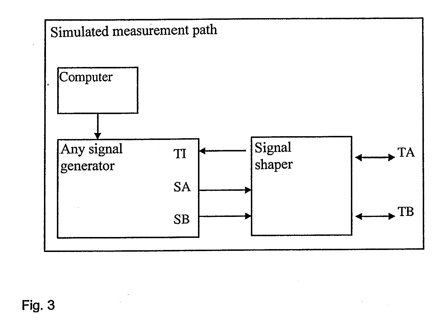
[0023]The device consists of a signal shaping unit and a
signal source. The transmitter is connected to the signal shaping unit via its acoustic
transducer terminals and the
signal source is connected to the signal shaping unit via the trigger input and the two signal outputs. The signal shaping unit generates a trigger impulse from the incoming emitted signals which is transferred to the
signal source. When the trigger impulse arrives, the signal source generates the two
required response signals. The response signals are forwarded by the signal shaping unit to the acoustic transducer terminals of the transmitter. An independent signal source is assigned to each acoustic transducer terminal of the transmitter. For this, the signal source contains two independent digital-to-analog
converters, each having its own memory for the storing of the digital representation of the response signal that is to be generated. The signal that is to be generated is calculated as a digital sequence of numbers of the instantaneous values of the response signal curve and stored in the memory of the digital-to-analog converter. These instantaneous values typically correspond to the instantaneous values of the
voltage curve of the response signal. The number of points to be stored is determined by the
clock rate of the digital-to-analog converter. The
clock rate must be high enough to conform to the sampling theorem. Therefore, the corresponding periodic time of the clock can be considerably larger than the target resolution of the transit times t1 and t2. The calculated digital images of the two response signals are stored directly in the memory and their output is started immediately when the trigger impulse is received. Conceivable, but not necessary, is a
delay by an integral multiple of the clock period. By doing this, it is possible to generate any signal shape for the two response signals assigned to the terminals T1 and T2. Given that the signal shape can be generated arbitrarily, the calculation can be made in such way that the transit time with respect to the emitted signal and the trigger impulse generated from it can also be adjusted arbitrarily. As a result, the resolution of the transit time is significantly smaller than the clock period of the digital-to-analog converter. Typically, the achievable resolution of the transit time is 1 / 1000 of the clock period. Therefore, the
delay lines as known and required for prior art are completely unnecessary. With this method, the calibration device is greatly simplified and its
measurement uncertainty is easily authenticated with respect to national standards because only the uncertainty the
clock generator determines the uncertainty of the calibration device.

