Stirling engine and control method thereof

a technology of rotating engine and control method, which is applied in the direction of closed-cycle machine/engine, hot gas positive displacement engine plant, etc., can solve the problems of reducing performance, foreign matter agglutinate, and increasing pressure of engine,

Inactive Publication Date: 2011-09-29
TOYOTA JIDOSHA KK
View PDF15 Cites 10 Cited by
  • Summary
  • Abstract
  • Description
  • Claims
  • Application Information

AI Technical Summary

Benefits of technology

[0008]The invention provides a Stirling engine in which reliability can be secured in a piston that is subjected to gas lubrication relativ...

Problems solved by technology

Meanwhile, in a Stirling engine having a piston that is subjected to gas lubrication relative to a cylinder, foreign matter may become interposed between the cylinder and the piston, and when the piston slides via the foreign matter, a surface pressure thereof may increase, causing the foreign matter to agglutinate.
As a result, a reduction in performance may occur.
Therefore, in a Stirling engine having a piston provided with a layer on...

Method used


Image

  • Stirling engine and control method thereof
  • Stirling engine and control method thereof
  • Stirling engine and control method thereof

Examples


first embodiment

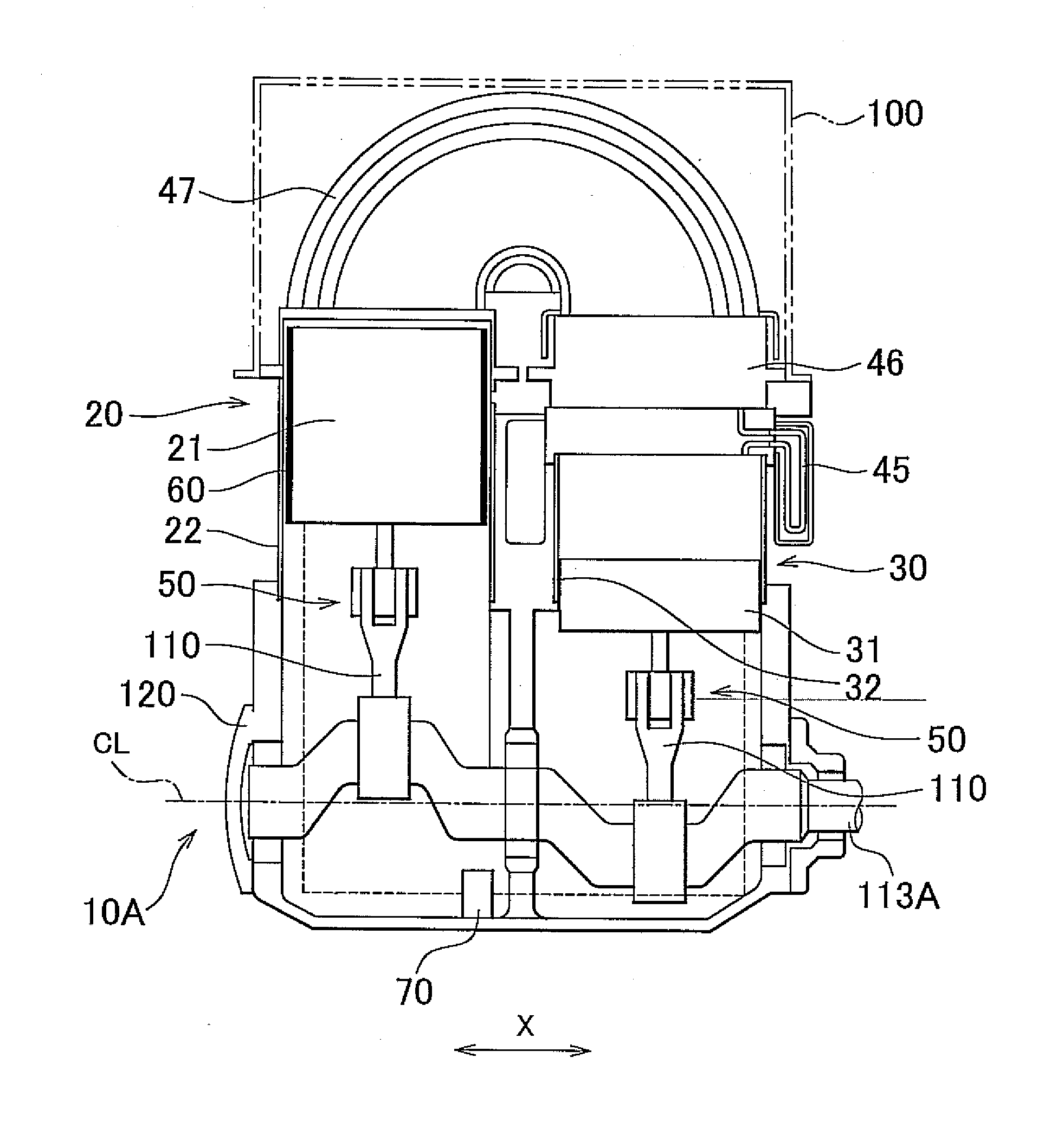
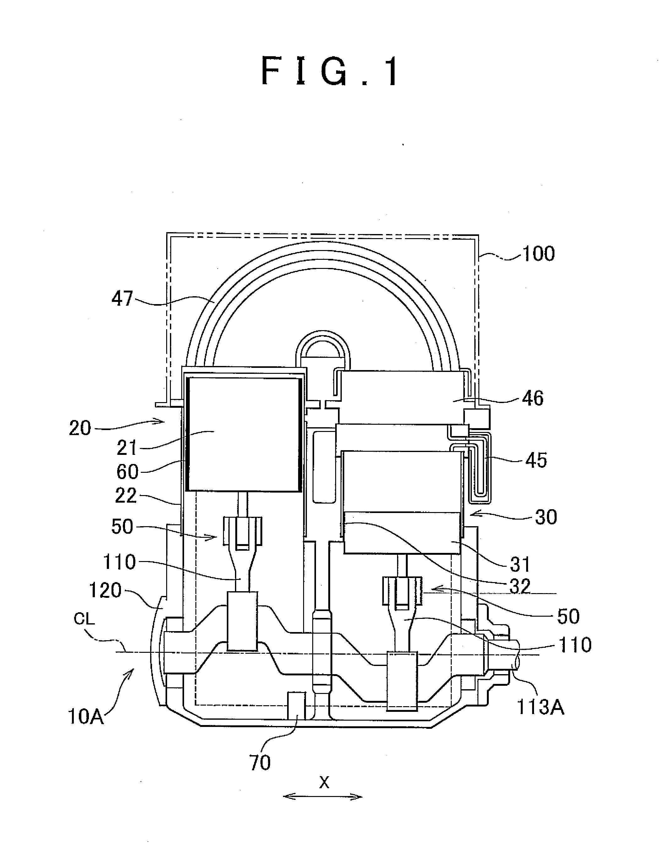
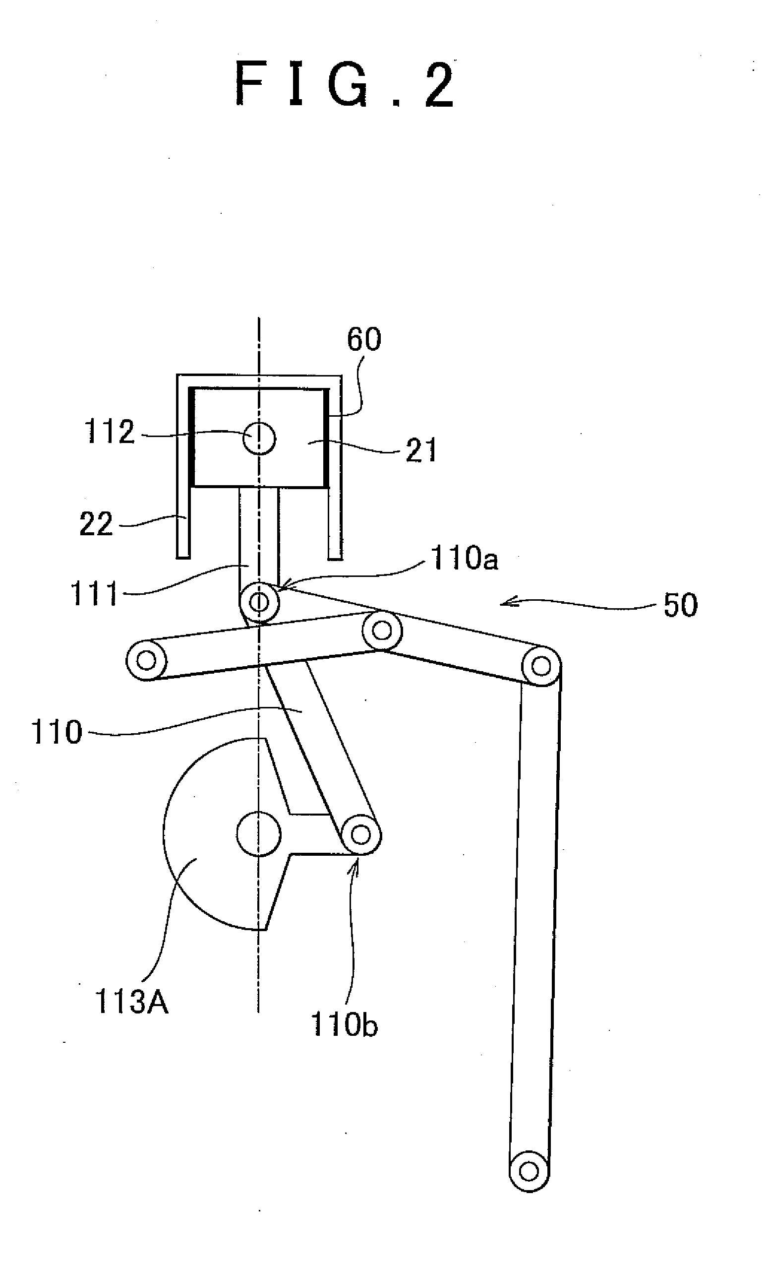
[0045]FIG. 1 is a schematic diagram showing a Stirling engine 10A according to this embodiment. The Stirling engine 10A is a two-cylinder α-type Stirling engine. The Stirling engine 10A includes two cylinder portions, namely a high-temperature side cylinder portion 20 and a low-temperature side cylinder portion 30, which are disposed in parallel series such that an extension direction of a crank axis CL and a cylinder arrangement direction X are parallel to each other. The high-temperature side cylinder portion 20 includes an expansion piston 21 and a high-temperature side cylinder 22, while the low-temperature side cylinder portion 30 includes a compression piston 31 and a low-temperature side cylinder 32. The compression piston 31 is provided at a phase difference to the expansion piston 21 so as to move at a delay of approximately 90°, in terms of a crank angle, relative to the expansion piston 21.

[0046]An upper portion space of the high-temperature side cylinder 22 serves as an ...

second embodiment

[0079]A Stirling engine 10B according to this embodiment is substantially identical to the Stirling engine 10A except that an ECU 8013 is provided in place of the ECU 80A. The ECU 80B is substantially identical to the ECU 80A except that the control means is realized in a manner to be described below. Accordingly, illustration of the Stirling engine 10B has been omitted. Likewise in the ECU 8013, the control means is realized to perform control for preventing the expansion piston 21 from contacting the high-temperature side cylinder 22 until the temperature Tp of the expansion piston 21 can be suppressed below the predetermined value γ while the engine operation is stopped. However, in the ECU 80B, the control means is realized to perform control for continuing the engine operation using the heat stored in the heater 47, i.e. received heat, after the heat supply from the high-temperature heat source is stopped until the piston temperature Tpb can be suppressed below the predetermine...

third embodiment

[0084]A Stirling engine 10C according to this embodiment is substantially identical to the Stirling engine 10A except that an ECU 80C is provided in place of the ECU 80A. The ECU 80C is substantially identical to the ECU 80A except that the control means is realized in a manner to be described below. Accordingly, illustration of the Stirling engine 10C has been omitted. Likewise in the ECU 80C, the control means is realized to perform control for preventing the expansion piston 21 from contacting the high-temperature side cylinder 22 until the temperature Tp of the expansion piston 21 can be suppressed below the predetermined value γ while the engine operation is stopped.

[0085]However, in the ECU 80C, the control means is realized to perform control for continuing the engine operation making maximum use of the heat stored in the heater 47 after the heat supply from the high-temperature heat source is stopped, and then beginning the operation to stop the engine operation such that th...


PUM


Abstract

A Stirling engine includes a high-temperature side cylinder and an expansion piston that is subjected to gas lubrication, or more specifically static pressure gas lubrication, relative to the high-temperature side cylinder and has a layer on an outer peripheral surface thereof, the layer being formed from a flexible material having a higher linear expansion coefficient than a base material of the expansion piston, wherein a booster pump and a ECU are provided as a contact avoiding device to prevent the expansion piston from contacting the high-temperature side cylinder when an engine operation is stopped until a temperature of the expansion piston can be suppressed below a predetermined value.

Description

CROSS-REFERENCE TO RELATED APPLICATIONS[0001]This application claims priority to Japanese Patent Application No. 2010-071644 filed on Mar. 26, 2010, which is incorporated herein by reference in its entirety including the specification, drawings and abstract.BACKGROUND OF THE INVENTION[0002]1. Field of the Invention[0003]The invention relates to a Stirling engine and a control method thereof, and more particularly to a Stirling engine including a piston that is subjected to gas lubrication relative to a cylinder and has a layer on an outer peripheral surface thereof, and a control method for the Stirling engine.[0004]2. Description of the Related Art[0005]In recent years, Stirling engines exhibiting excellent theoretical thermal efficiency have come to attention with the aim of retrieving exhaust heat from factories and exhaust heat from internal combustion engines installed in vehicles such as passenger automobiles, buses and trucks. High thermal efficiency can be expected of a Stir...

Claims


Application Information

Patent Timeline
IPC IPC(8): F02G1/053F01B31/10
CPCF02G1/043F16N15/00F02G2270/40
Inventor YAGUCHI, HIROSHISAWADA, DAISAKUKATAYAMA, MASAAKI
Owner TOYOTA JIDOSHA KK
Why Eureka
Try Eureka