Differential signal cable, and cable assembly and multi-pair differential signal cable using the same

a technology of differential signal and cable, applied in the field ofdifferential signal cables, can solve the problems of easy disturbance of uniformity of characteristic impedance, degradation of signal quality, etc., and achieve the effects of minimizing characteristic impedance mismatch, increasing disturbance, and increasing skew

Active Publication Date: 2011-09-29
HITACHI CABLE +1
View PDF4 Cites 24 Cited by
  • Summary
  • Abstract
  • Description
  • Claims
  • Application Information

AI Technical Summary

Benefits of technology

[0030]The present invention provides a differential signal cable for transmitting high-speed digital differential signals of several Gbit/s or more that permits minimizing characteristic impedance mismatch, which may appear when connecting to a device such as a printed circuit board having a built-in connector, at the ...

Problems solved by technology

In the transmission of high-speed signals of several Gbit/s, characteristic impedance must be maintained uniform as much as possible; otherwise, undesirable signal reflection will appear causing degradation in signal quality.
Uniformity of characteristic imp...

Method used


Image

  • Differential signal cable, and cable assembly and multi-pair differential signal cable using the same
  • Differential signal cable, and cable assembly and multi-pair differential signal cable using the same
  • Differential signal cable, and cable assembly and multi-pair differential signal cable using the same

Examples


Embodiment Construction

[0041]The following explains a preferred embodiment of the present invention referring to drawings attached.

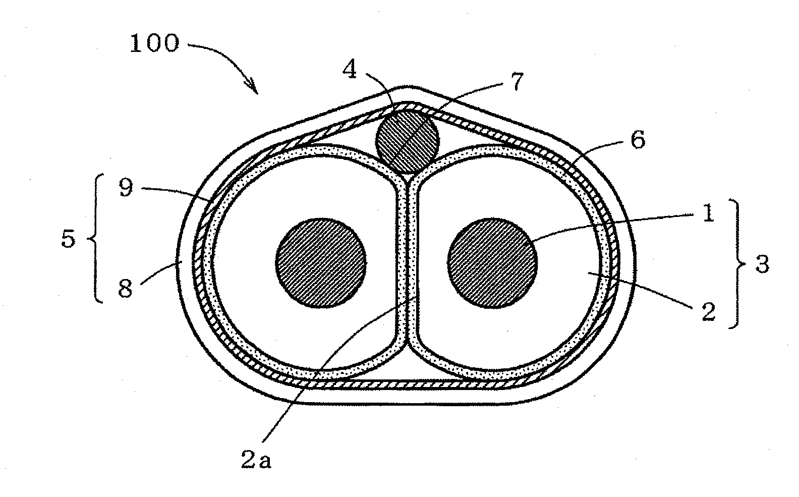
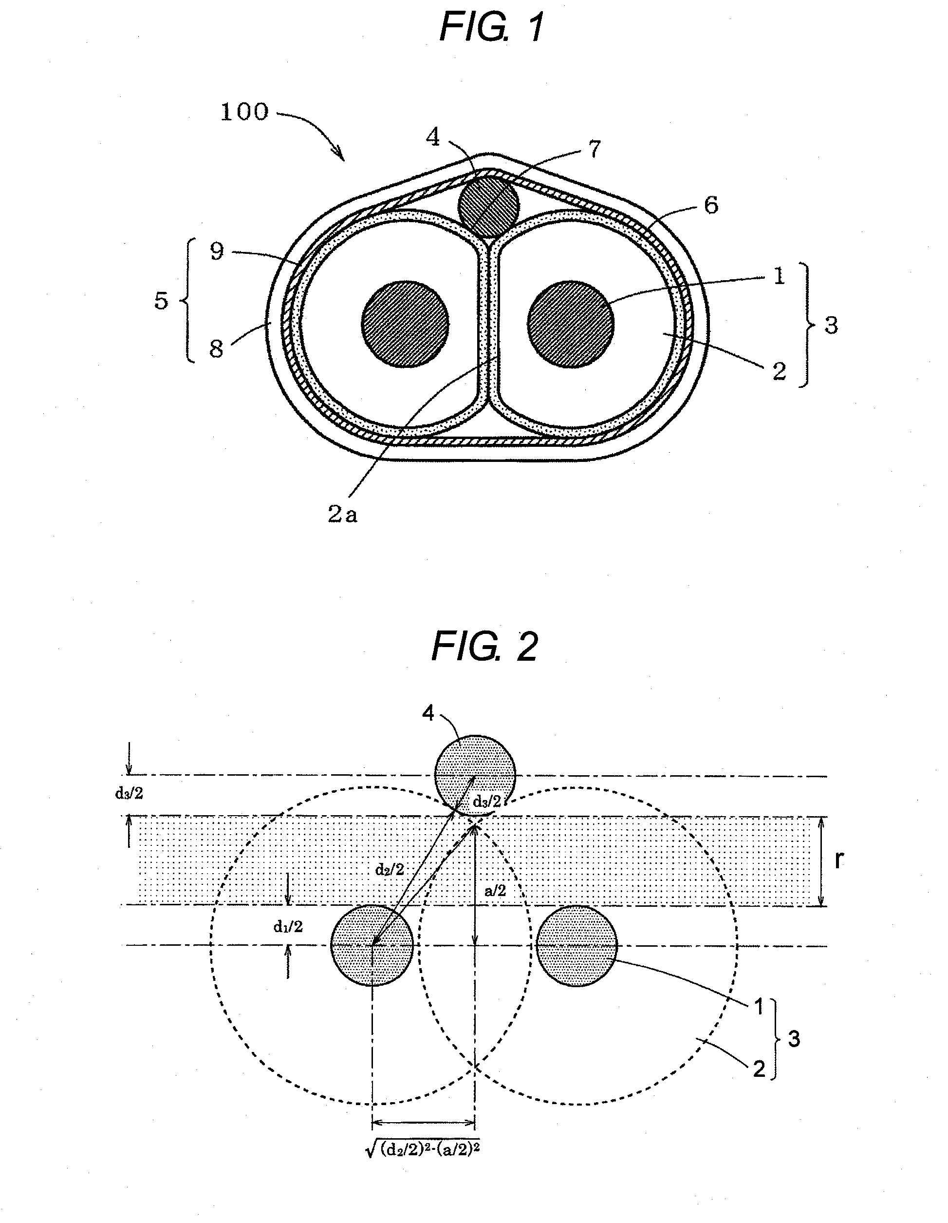
[0042]FIG. 1 is a sectional view of a differential signal cable of an embodiment of the present invention.

[0043]As illustrated in FIG. 1, a differential signal cable 100 in an embodiment of the present invention is comprised of two insulated wires 3, each of which is comprised of a signal conductor 1 and an insulator 2 jacketing the conductor 1, arranged parallelly in an intimate contact; a fusion layer 6 provided on the surface of each of the two insulated wires 3; a drain wire 4 placed longitudinally in a recess 7 created in the interstice between the two insulated wires 3; and a shield tape 5 lapping around the two insulated wires 3 and the drain wire 4 together.

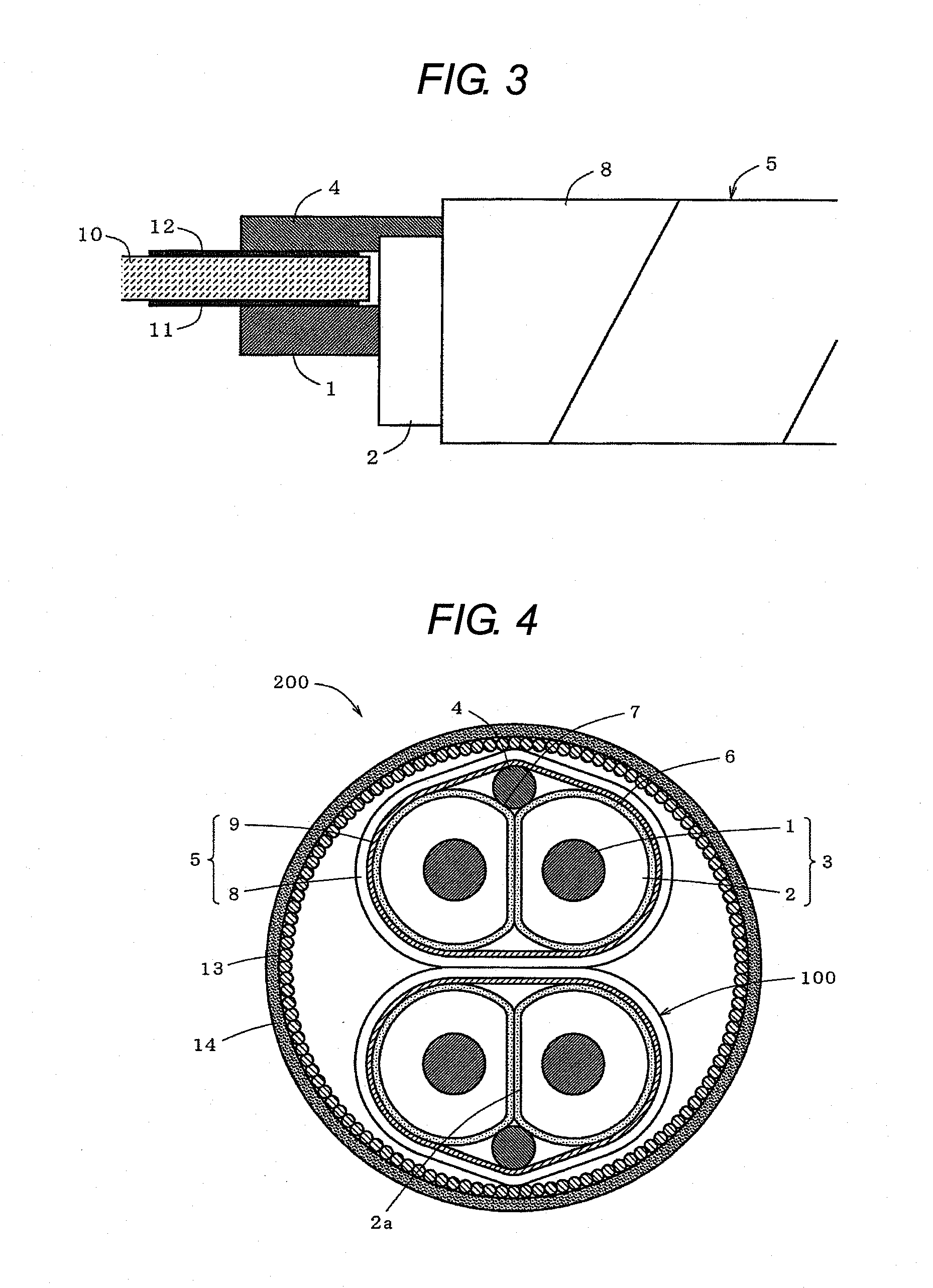
[0044]The insulated wire 3 is formed by jacketing the conductor 1 with the insulator 2 supplied from an extruder.

[0045]As the conductor 1 for the insulated wire 3, a solid wire or stranded wires of good electrical c...


PUM


Abstract

A differential signal cable for transmitting high-speed digital differential signals of several Gbit/s or more is provided to minimize characteristic impedance mismatch and to repress increase in the skew, or increase in disturbance due to differential-mode to common-mode conversion. A differential signal cable comprises two insulated wires arranged parallelly in a contact, each of said two insulated wires comprising a conductor and an insulator jacketing the conductor; a fusion layer provided on the surface of each of said two insulated wires; a drain wire placed longitudinally in a recess created in the interstice between said two insulated wires; and a shield tape lapping around said two insulated wires and said drain wire together, wherein a surface of said insulator of each of said two insulated wires is partially deformed so as to have a flat portion and said two insulated wires are fused each other at said flat portions.

Description

[0001]The present application is based on Japanese Patent Application No. 2010-065981 filed on Mar. 23, 2010, the entire contents of which are incorporated herein by reference.TECHNICAL FIELD[0002]The present invention relates to a differential signal cable for transmitting high-speed digital signals of several Gbit / s or more over a distance from several meters to several ten meters with less degradation of signal waveforms. The present invention further relates to a cable assembly and a multi-pair differential signal cable each using such cable.BACKGROUND OF THE INVENTION[0003]In servers, routers, or storage devices that handle high-speed digital signals of several Gbit / s or more, a differential signal transmission system is employed for transmitting signals among such equipment or between circuit boards within such equipment. The differential signal transmission system transmits a signal in a two-phase style of signal on two conductors: one normal phase and the other 180-degree in...

Claims


Application Information

Patent Timeline
IPC IPC(8): H05K1/00H01B11/06
CPCH01B11/1016H01B11/203H01B11/1091H01B11/1025
Inventor SUGIYAMA, TAKAHIRONONEN, HIDEKITSUKAMOTO, YOSHINORI
Owner HITACHI CABLE
Why Eureka
Try Eureka