Display having split sub-pixels for multiple image display functions

a display function and sub-pixel technology, applied in the field of display and sub-pixels, can solve the problems of limiting the application of the display mode to relatively niche markets, requiring additional liquid crystal switch cells, and only having 33% resolution and approximately 33% brightness

Inactive Publication Date: 2011-09-29
SHARP KK
View PDF17 Cites 75 Cited by
  • Summary
  • Abstract
  • Description
  • Claims
  • Application Information

AI Technical Summary

Benefits of technology

[0044]According to a further, the pitch of the structure on the parallax optic may be chosen to enable even vie...

Problems solved by technology

However, GB2405542 does not teach explicitly how to realise a privacy display nor does it describe how to electronically switch between the public wide view mode and a private narrow view mode of said privacy display.
The main disadvantage of the public mode is that images have only 33% resolution and approximately 33% brightness compared to an identical image panel without the parallax optic attached.
This relatively poor public mode performance limits the application of the display mode to relatively niche markets.
The main disadvantage of both GB2426352 and U.S. Pat. No. 7,359,105 is that, in order to realise a display with extra image functions, an additional liquid crystal switch cell is required.
The extra weight and thickness are very undesirable, especially for mobile display products such as mobile phones, laptop personal computers etc.
A display that does not have the capability of switching between a public wide view mode and a private narrow view mode has an inherent disadvantage over displays that are switchable between the two modes.
A key disadvantage to autostereoscopic displays which use a ...

Method used


Image

  • Display having split sub-pixels for multiple image display functions
  • Display having split sub-pixels for multiple image display functions
  • Display having split sub-pixels for multiple image display functions

Examples


Embodiment Construction

[0081]The present invention is now described with reference to the figures, wherein like reference numerals are used to refer to like elements throughout.

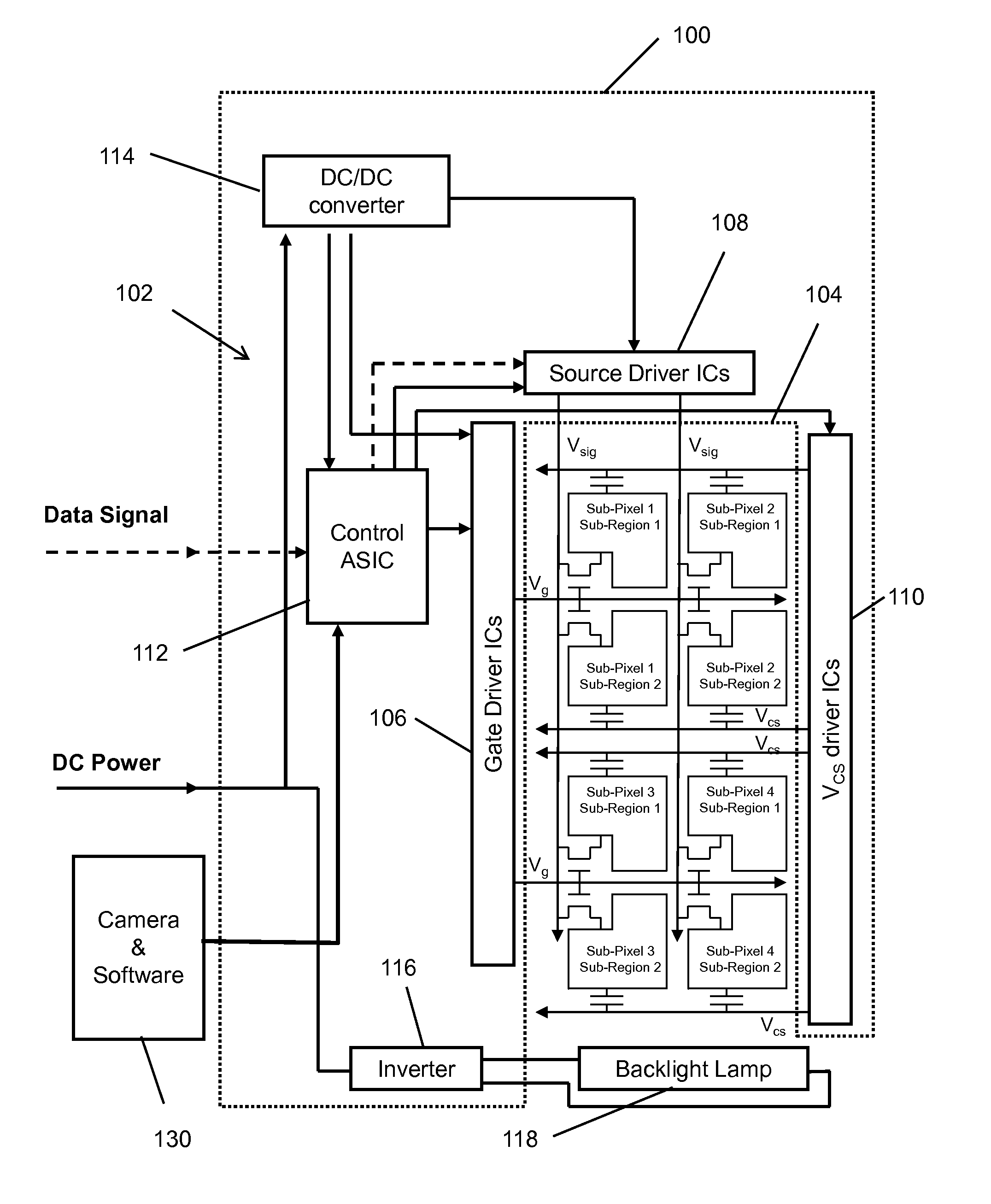
[0082]FIG. 3a illustrates a schematic of capacitively coupled driven split sub-pixel type multi-view display 100 in accordance with an exemplary embodiment of the present application. The display 100 includes control electronics 102 and a liquid crystal (LC) display panel 104. The control electronics 102 are designed, as conventional, to receive digital image data and to output analogue signal voltages for each pixel included in the liquid crystal (LC) panel 104. In addition, the control electronics 102 provide timing pulses and a common voltage for the counter electrode of all the pixels in the LC panel 104.

[0083]More particularly, the control electronics 102 are configured specifically to the electro-optical characteristics of the LC panel 104 so as to output signal voltages which are dependent on the input image data in such a w...


PUM


Abstract

A display which includes a plurality of sub-pixels each split into a plurality of sub-regions. Each sub-pixel includes a single gate line and a single signal line, and each sub-region within a given sub-pixel includes a corresponding storage capacitor line. An optical element cooperatively combines with the plurality of sub-pixels to create distinct angularly dependent brightness functions in association with corresponding sub-regions within the sub-pixels. Control electronics are configured to provide image data levels in the form of signal data voltages to each sub-region included within each sub-pixel via the gate line and signal line included within the sub-pixel; and to independently modify the signal data voltages provided to each sub-region within the sub-pixels via the corresponding storage capacitor lines whereby the display operates in accordance with at least two different image functions.

Description

TECHNICAL FIELD[0001]The invention relates to a display and sub-pixels included therein. Such a display may be used as a directional display in, for example, a mobile phone, portable media players, games devices, a laptop personal computer, a television, a desktop monitor, etc. Such a display device is capable of at least two different image display modes among, for example, a conventional display, a privacy display, an autostereoscopic 3D display.BACKGROUND ART[0002]Multiple users can view the same image on a conventional display device simultaneously. The properties of a conventional display device are such that viewers can see the same image from different angles with respect to the display (hereafter “Public Mode”). This is effective in applications where many users require the same information from the display—such as, for example, displays of departure information at airports and railway stations. However, there are many applications where it would be desirable for an individu...

Claims


Application Information

Patent Timeline
IPC IPC(8): G06T1/00G09G3/34G02B27/22G02B30/27G02B30/30
CPCG02B27/2214G09G3/003G09G3/3659G09G2300/043G09G2358/00G09G2300/0447G09G2320/028G09G2354/00G09G2300/0443G02B30/27G02B30/30
Inventor SMITH, NATHAN JAMESBROUGHTON, BENJAMIN JAMESZEBEDEE, PATRICKMATHER, JONATHAN
Owner SHARP KK
Why Eureka
Try Eureka