
Method of printing test pattern and inkjet recording apparatus

a test pattern and inkjet recording technology, applied in the direction of printing, other printing apparatus, etc., can solve the problems of dummy shots actually soiling the nozzle surface, affecting the quality of printing, and increasing the viscosity of the ink, so as to improve the quality of printing. , the effect of maintaining recording stability

Inactive Publication Date: 2011-09-29
FUJIFILM CORP
View PDF9 Cites 18 Cited by
  • Summary
  • Abstract
  • Description
  • Claims
  • Application Information

AI Technical Summary

Benefits of technology

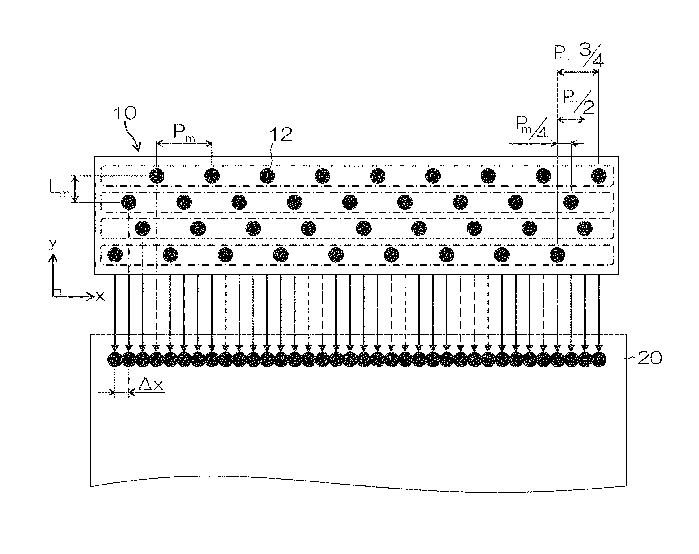
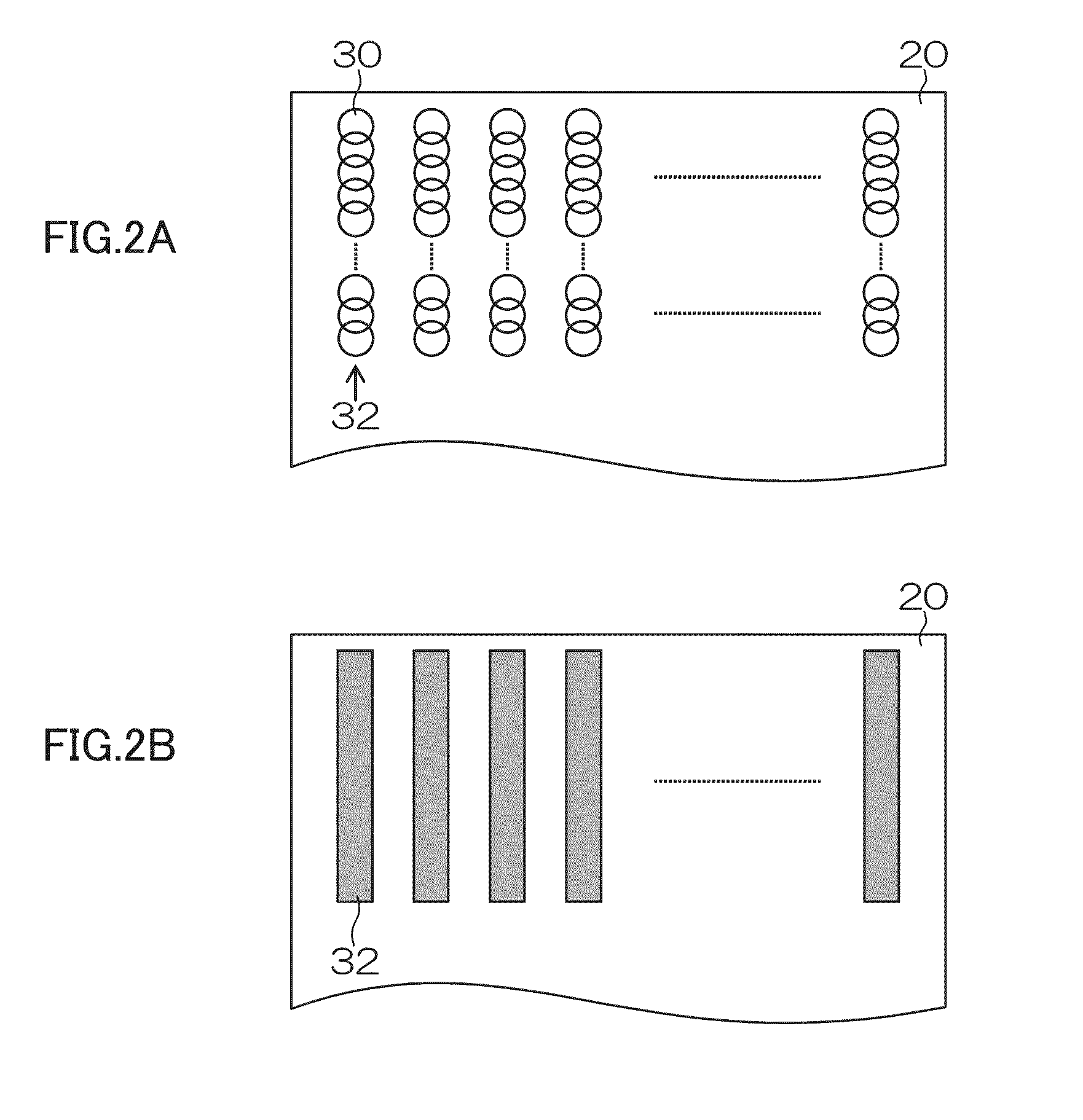
[0011]The present invention has been contrived in view of these circumstances, an object thereof being to provide a method of printing a test pattern having a high effect in preventing blockages, and to provide an inkjet recording apparatus capable of increasing throughput by reducing the number of actual maintenance processes (application of pressure, suction purging, wiping, etc.) carried out outside the range of the paper.

Problems solved by technology

In an inkjet head, drying occurs in the vicinity of the nozzle opening sections in nozzles which have not performed ejection for a long period of time, and as a result of this there is a problem in that the ink viscosity increases and blockages occur.
However, in recent heads having increased density, there is a marked problem (e.g., the occurrence of air currents or cross-talk) due to a plurality of nozzles being driven simultaneously, and the performing of dummy shots actually ends up soiling the nozzle surface.
For example, in Japanese Patent Application Publication No. 2001-225485, by carrying out dummy shots from all of the nozzles, disturbance in the air flow below the nozzle surface arises and fluid interaction (cross-talk), or the like, occurs between adjacent nozzles which are connected to the same flow channel in the head, thus causing ejection to become instable.
Hence, there is a possibility that liquid separated from the meniscus will adhere to the vicinity of the nozzle openings and degrade the state of the nozzle surface.
This is a marked issue in the case of high-density nozzles in a matrix head, in which a plurality of nozzles are arranged in a matrix configuration.
Furthermore, with an ejection operation based on the application of high voltage, air bubbles are incorporated when the meniscus returns after ejection of a droplet and there is a risk of air bubbles entering into the nozzle.
A maintenance operation of this kind takes time and put limits on the extent to which the effective printing speed (throughput) can be raised.

Method used


Image

  • Method of printing test pattern and inkjet recording apparatus
  • Method of printing test pattern and inkjet recording apparatus
  • Method of printing test pattern and inkjet recording apparatus

Examples


first embodiment

of Control of Printing Operation in Inkjet Recording Apparatus

[0107]FIG. 8 is a flowchart showing a first embodiment of control of a printing operation in an inkjet recording apparatus according to the embodiment of the present invention.

[0108]When the power supply to the apparatus is switched on (step S10), either manually or by automatic control from an external source, then judgment of the input of a print signal is performed (step S12). If there is no input of a print signal, the processing in step S12 is looped and the procedure awaits the input of a print signal. The print signal may be issued in accordance with an operation performed by an operator to instruct execution of a print, or may be issued from an external apparatus, such as a host computer. When a print signal is input, a YES verdict is produced at step S12, and the procedure advances to step S14.

[0109]At step S14, a test pattern according to the present embodiment is printed. For example, the ejection force is rais...

second embodiment

of Control of Printing Operation in Inkjet Recording Apparatus

[0127]When the defective ejection nozzles have been restored, it is possible for these nozzles to be used again for printing. When the restored nozzles are used for printing, desirably, a test pattern is formed again and it is checked whether the nozzles can be used. FIG. 12 shows an example of this.

[0128]FIG. 12 is a flowchart showing a further example of control of a printing operation in an inkjet recording apparatus according to an embodiment of the present invention. In FIG. 12, the steps which are the same as or similar to those in FIG. 8 are denoted with the same step numbers and description thereof is omitted here.

[0129]In the example in FIG. 12, after ejection from the defective nozzles in step S20, the procedure advances to step S22 and a test pattern is output again. The ejection conditions in this case may be the same as, or different to, the first time in step S14. For example, in step S22, it is possible to ...


PUM


Abstract

A test pattern is printed for ascertaining ejection characteristics of nozzles arranged in a recording head in an inkjet recording apparatus which forms and records a desired image on a recording medium by performing ejection of droplets of liquid from the nozzles and deposition of the droplets onto the recording medium. Ejection of droplets of the liquid from the recording head is performed by applying, to the recording head, a drive signal having a test waveform in which at least one of a voltage, a frequency and a waveform shape is altered with respect to a drive signal having a recording waveform which is applied to the recording head when the desired image is formed, to thereby perform the ejection with an increased ejection force compared with a case where the drive signal having the recording waveform is applied; and the test pattern is formed by the ejected droplets.

Description

BACKGROUND OF THE INVENTION[0001]1. Field of the Invention[0002]The present invention relates to a method of printing a test pattern for detecting blockages and the like in nozzles of an inkjet head, and to maintenance technology for eliminating ejection defects.[0003]2. Description of the Related Art[0004]In an inkjet head, drying occurs in the vicinity of the nozzle opening sections in nozzles which have not performed ejection for a long period of time, and as a result of this there is a problem in that the ink viscosity increases and blockages occur. In an inkjet recording apparatus, an operation is carried out to discharge ink in the nozzle opening sections by performing preliminary ejection of ink (also referred to as “dummy shot” or “dummy ejection”) after a prescribed time interval or before starting printing. For example, Japanese Patent Application Publication No. 2001-225485 discloses a method in which at least one of the number, interval, ejection period or ejection volta...

Claims


Application Information

Patent Timeline
Patent Type & Authority Applications(United States)
IPC IPC(8): B41J29/393
CPCB41J2/2146B41J2/16579B41J29/393B41J2029/3935B41J2/1652
Inventor NISHIKAWA, BAKU
Owner FUJIFILM CORP
Learn More