Stereoscopic picture display, method of manufacturing the same and stereoscopic picture display method
a stereoscopic and picture technology, applied in the field of stereoscopic picture display, method of manufacturing the same, and stereoscopic picture display method, can solve the problems of large system, complex control, and inability to achieve practical image quality, and achieve easy manufacturability, simple configuration, and high reproducibility
Inactive Publication Date: 2011-09-29
SONY CORP
View PDF8 Cites 8 Cited by
- Summary
- Abstract
- Description
- Claims
- Application Information
AI Technical Summary
Benefits of technology
[0021]In the 3D video display in NPTL 2, the stereoscopic picture is displayed by light passing through a plurality of vertical lines arranged around the circumferential surface of the rotating body, so use efficiency of light rays may be reduced to cause large energy loss.
[0026]The present invention is made to solve the above-described issues, and it is an object of the invention to provide a stereoscopic picture display allowing a stereoscopic picture to be viewable from all directions with high reproducibility without complicating a stereoscopic display mechanism, compared to related art, a method of manufacturing the same, and a stereoscopic picture display method.
[0038]In the method of manufacturing a stereoscopic picture display according to the embodiment of the invention, the stereoscopic picture display with a simple configuration in which the light-emitting element array is mounted in the cylindrical rotation section is manufactured; therefore, a stereoscopic picture display allowing a stereoscopic picture to be viewed from all directions with high reproducibility is easily manufacturable without complicating a stereoscopic display mechanism, compared to related art.
Problems solved by technology
In the stereoscopic picture display in NPTL 1, the limited viewing angle screen, the rotation mechanism, the top mirror, the bottom mirrors, the projector and the personal computer are necessary, so a system is large and control is complicated.
As bundles of rays from a plurality of pixels on the display surface are allotted to the respective aperture parts or lenses, there is an issue that practical image quality is not obtainable.
Method used
View moreImage
Smart ImageViewing Examples
Examples
seventh embodiment (
7. Seventh Embodiment (Optimization of slit width)
eighth embodiment (
8. Eighth Embodiment (Optimization of light-emission timing)
ninth embodiment (
9. Ninth Embodiment (Viewing example of stereoscopic pictures by displays of respective embodiments)
Login to View More PUM
 Abstract
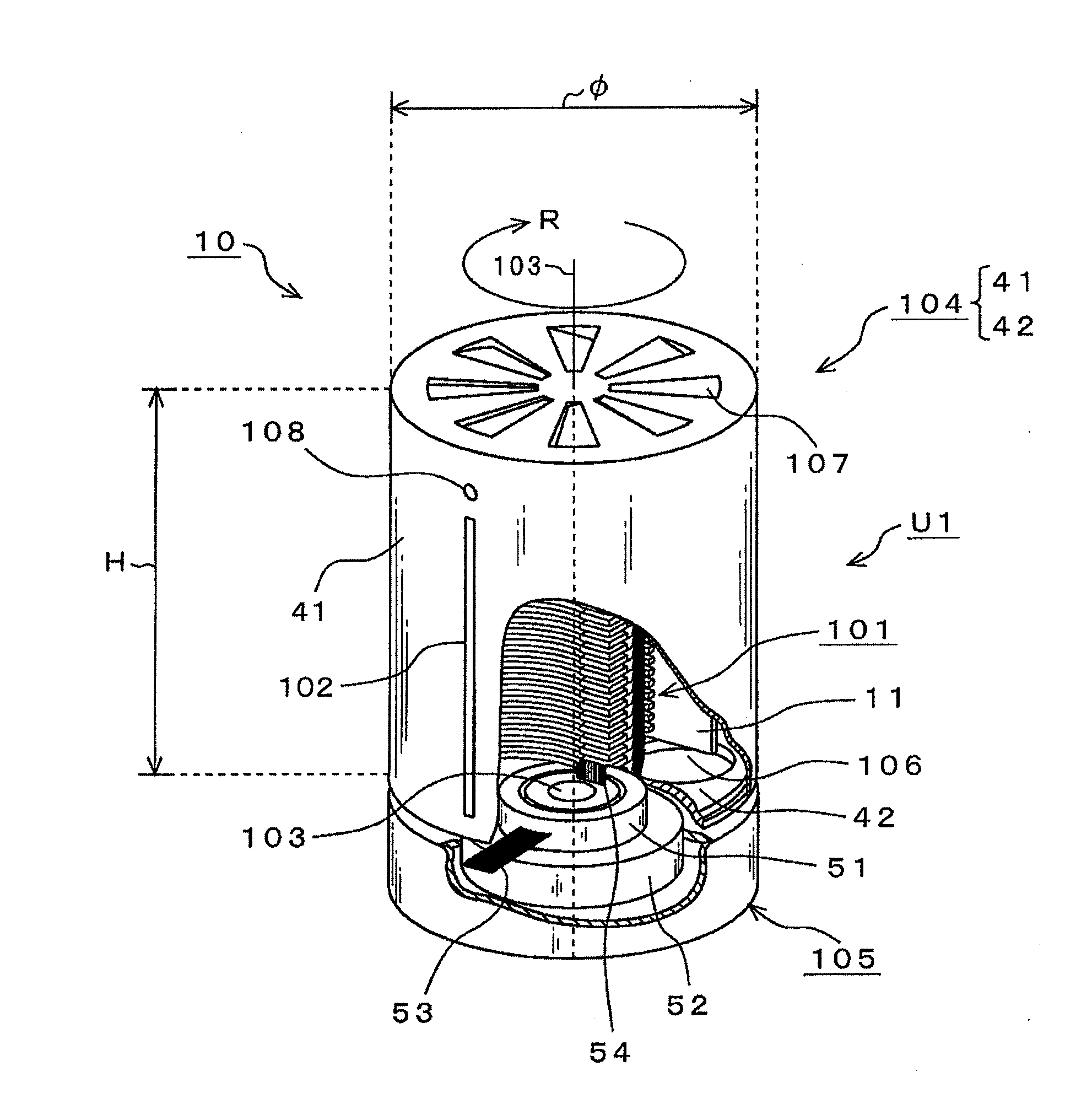
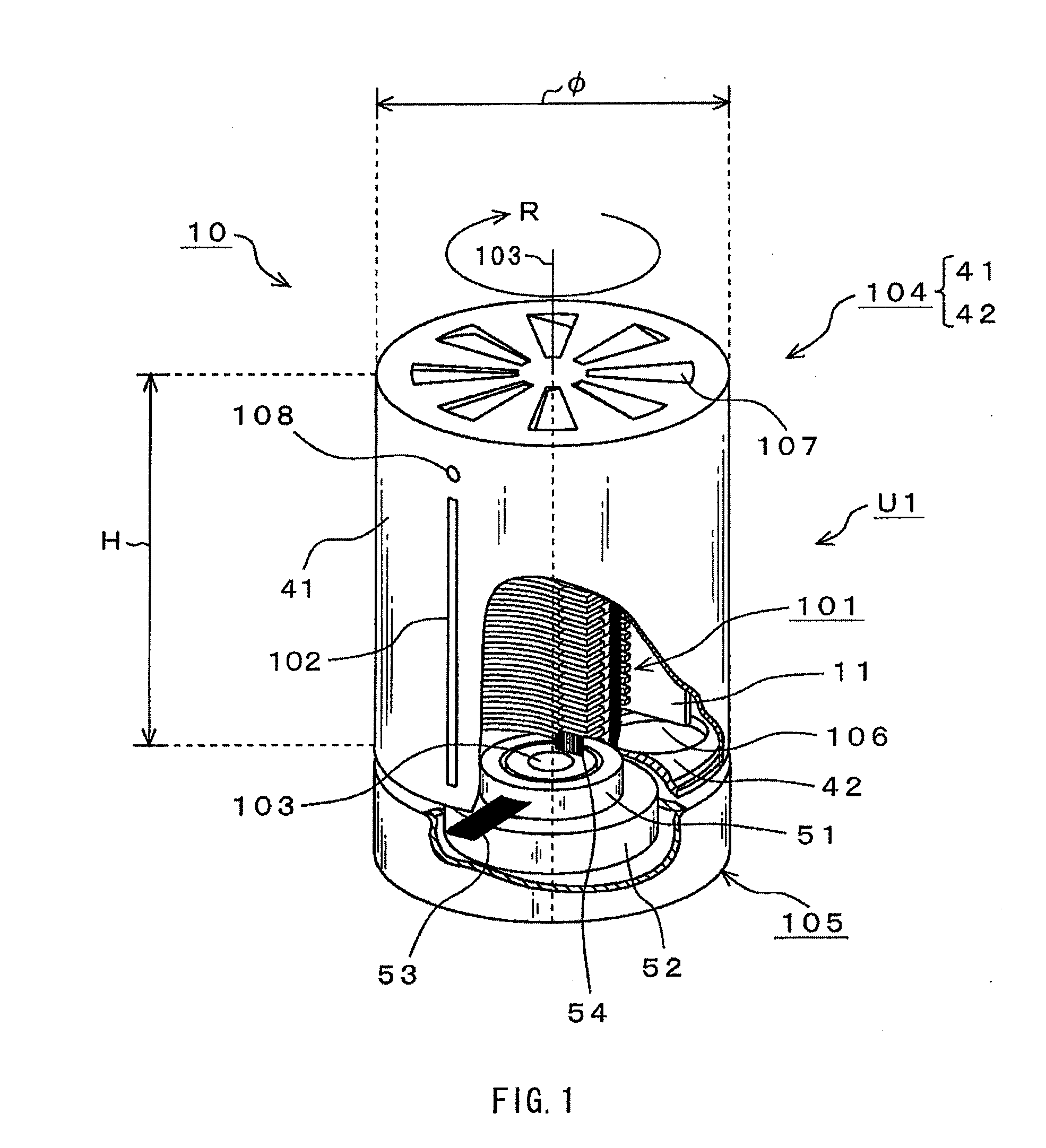
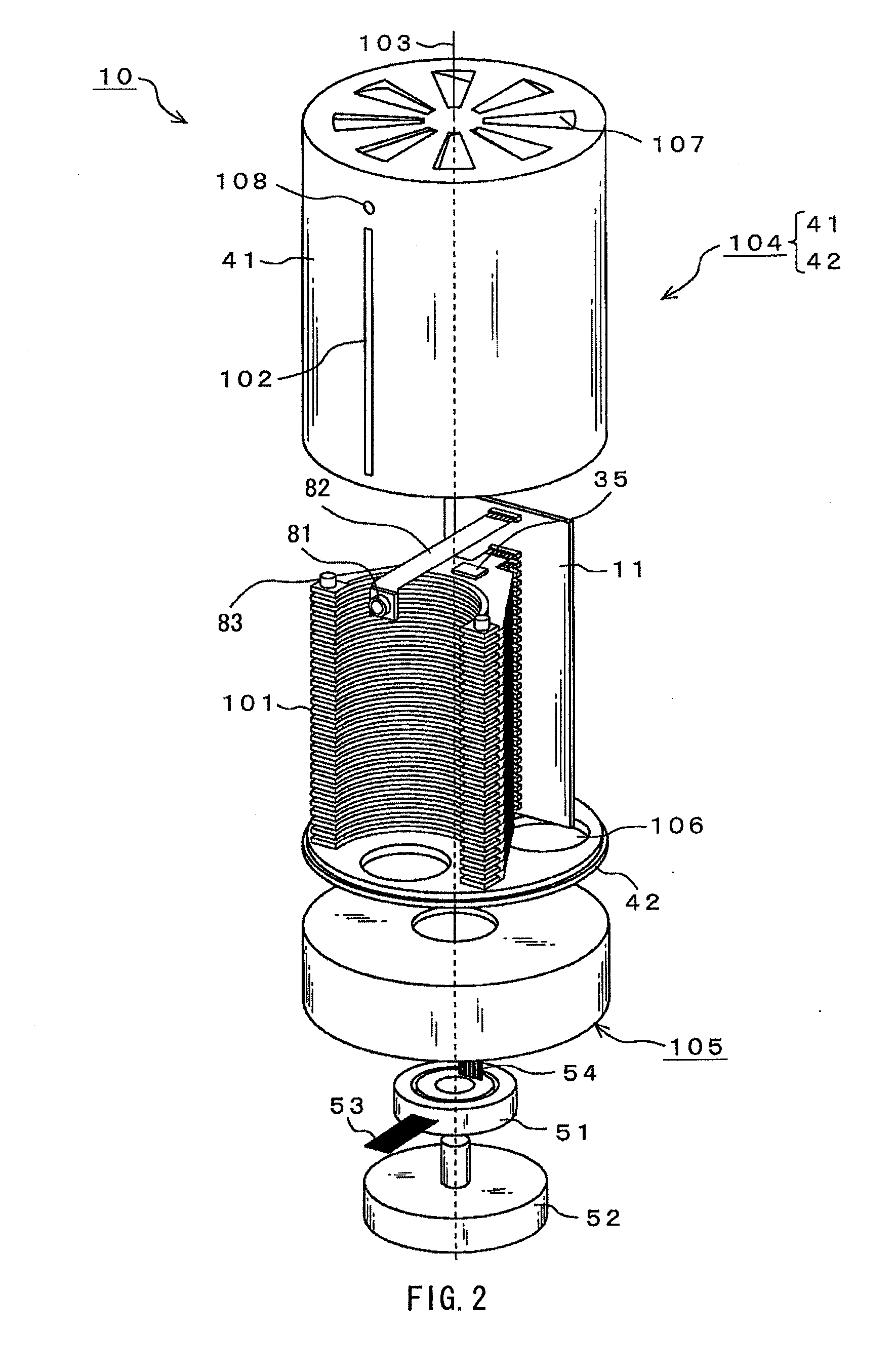
A stereoscopic picture is viewable from all directions with high reproducibility without complicating a stereoscopic display mechanism, compared to related art. A cylindrical rotation section 104 rotating around a rotation shaft as a rotation center, a two-dimensional light-emitting element array 101 mounted in the rotation section and having a light-emission surface formed of a plurality of light-emitting elements arranged in a matrix, and a slit 102 arranged in a circumferential surface of the rotation section in a position facing the light-emission surface are included. As the two-dimensional light-emitting element array 101, a two-dimensional light-emitting element array including a curved portion with a concave surface which is formed as a light-emission surface is used. The plurality of light-emitting elements emit light, which corresponds to orientation of the light-emission surface, to outside of the rotation section through the slit 102.
Description
CROSS REFERENCES TO RELATED APPLICATIONS[0001]The present application is a 371 U.S. National Stage filing of PCT / JP2009 / 070672, filed Dec. 10, 2009, which claims priority to Japanese Patent Application Number JP 2009-242716 filed Oct. 21, 2009 and the Japanese Patent Application Number JP 2008-317522, filed Dec. 12, 2008, all of which are incorporated herein by reference.TECHNICAL FIELD[0002]The present invention relates to a stereoscopic picture display capable of displaying a stereoscopic picture around an entire circumference thereof, a method of manufacturing the same and a stereoscopic picture display method.BACKGROUND ART[0003]A large number of integral imaging-based omnidirectional stereoscopic picture displays picking up images of a subject from all directions or reproducing a stereoscopic picture of an entire circumference of a subject based on two-dimensional picture information for stereoscopic picture display formed by a computer have been proposed. For example, NPTL 1 d...
Claims
Login to View More Application Information
Patent Timeline
 IPC IPC(8): H04N13/04H01L33/00H04N13/393
CPCG02B27/2264G03B35/22G09G3/005H04N13/0493G03B35/24H04N13/393G02B30/24G02B30/27H04N13/00
Inventor ITO, KATSUHISAEGUCHI, NAOYAKIKUCHI, HIROKITAJIRI, SHINICHIROKOBAYASHI, IZUSHIYASUNAGA, HIROAKI
Owner SONY CORP
Features
- R&D
- Intellectual Property
- Life Sciences
- Materials
- Tech Scout
- Unparalleled Data Quality
- Higher Quality Content
- 60% Fewer Hallucinations
Learn More Browse by: Latest US Patents, China's latest patents, Technical Efficacy Thesaurus, Application Domain, Technology Topic, Popular Technical Reports.
© 2025 PatSnap. All rights reserved.Legal|Privacy policy|Modern Slavery Act Transparency Statement|Sitemap|About US| Contact US: help@patsnap.com


