Mounting position measuring device

a technology of mounting position and measuring device, which is applied in the direction of instruments, lighting and heating apparatus, optical elements, etc., can solve the problems of difficult to ensure manufacturing accuracy, high manufacturing cost, and large size of mirrors, and achieve the enhancement of the mounting posture of each facet 31 and the work efficiency of the facet mounting work. , the effect of quick and accurate measurement and adjustmen

Inactive Publication Date: 2011-09-29
MITSUI ENG & SHIPBUILD CO LTD
View PDF5 Cites 13 Cited by
  • Summary
  • Abstract
  • Description
  • Claims
  • Application Information

AI Technical Summary

Benefits of technology

[0023]A device example of the mounting posture measuring device according to the present invention is shown in FIG. 1. As shown in FIG. 1, in the mounting posture measuring device 1 according to the present invention, an emitted laser beam emitted from each of the laser generators 11 is reflected by a corresponding one of the facets 31. Additionally, the reflected laser beam 52 which is a reflected beam produced by this reflection is received by the laser point measuring unit 12, and the mounting posture of the facet 31 is measured from that position. Hence, the measurement can be made in a limited space such as a factory. Furthermore, because the laser beam which is an actual beam of light is used, the accuracy of the mounting posture of each facet 31 is enhanced compared with that achieved by the conventional method using a pattern.
[0024]Moreover, the mounting posture measuring device 1 according to the present invention is configured to be capable of coping with the adjustment of the facets 31 even in a case where the distances of the respective facets 31 to the focal point 51 are different from one another. For instance, the focal lengths of the respective multiple heliostats 3 used for the solar therm

Problems solved by technology

However, its manufacturing costs are high.
In addition, it is difficult to sec

Method used


Image

  • Mounting position measuring device
  • Mounting position measuring device
  • Mounting position measuring device

Examples


embodiment 1

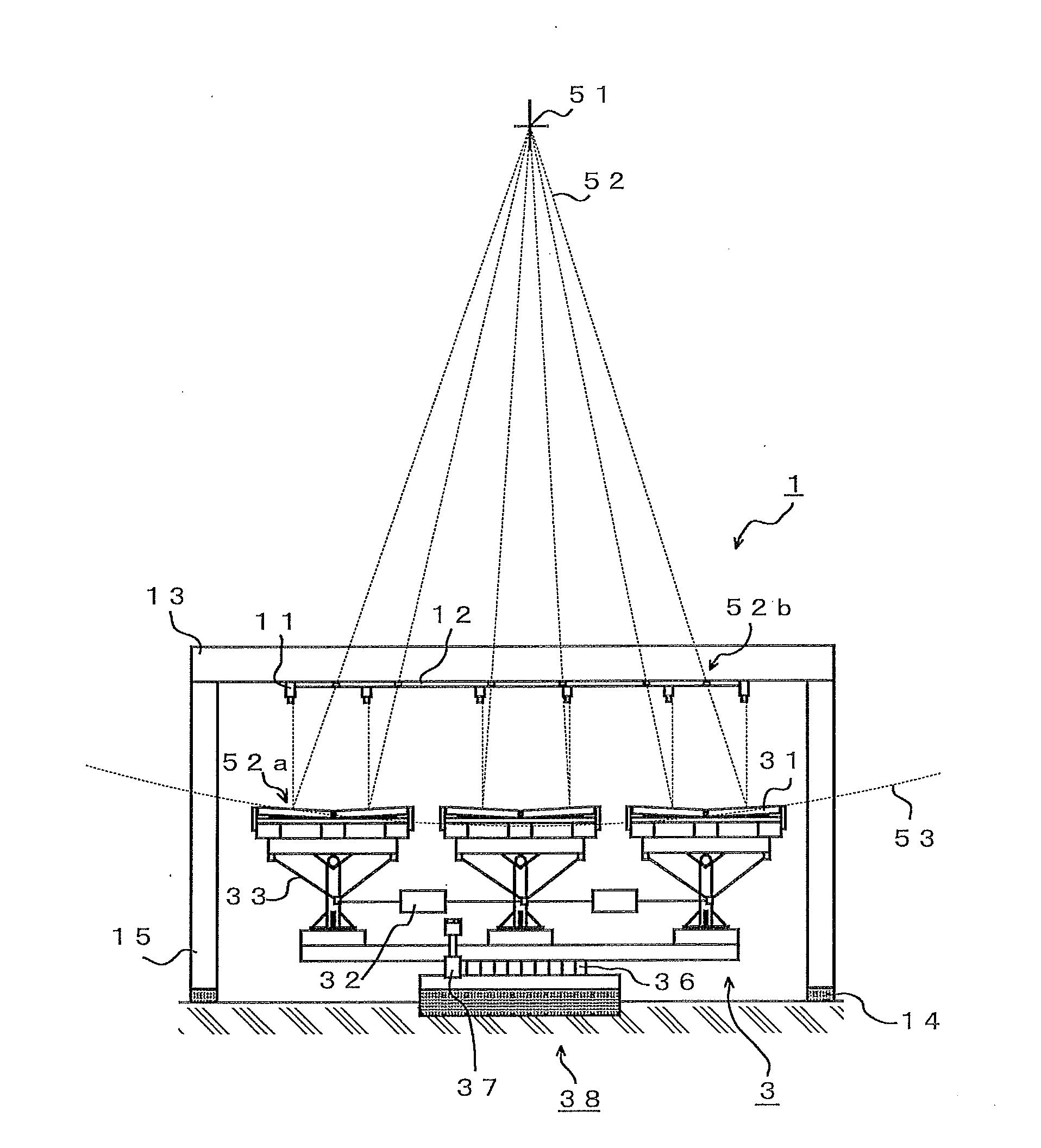
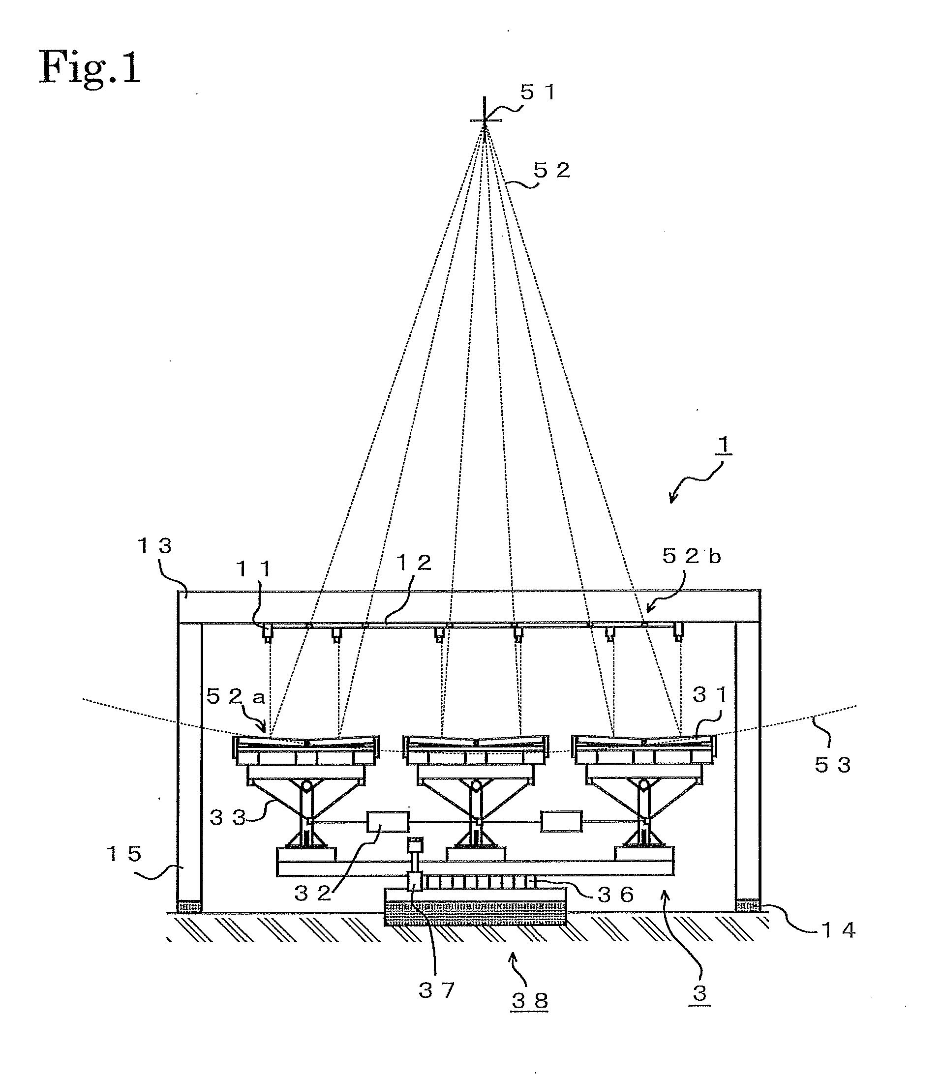
[0059]FIG. 6 shows a configuration of a different embodiment of the mounting posture measuring device 1. A laser distance measuring unit 15 for measuring distances by use of laser beams is installed on the supporting member 13 shaped like an arch, and in such a way that the laser distance measuring unit 15 moves along a reference line 54 which is arbitrarily determined in such a way as to be in parallel with the supporting member 13. The supporting member 13 includes the movement mechanism 14. Furthermore, FIG. 6 shows how the mounting posture measuring device 1 is placed above the heliostats 3 which are measurement subjects.

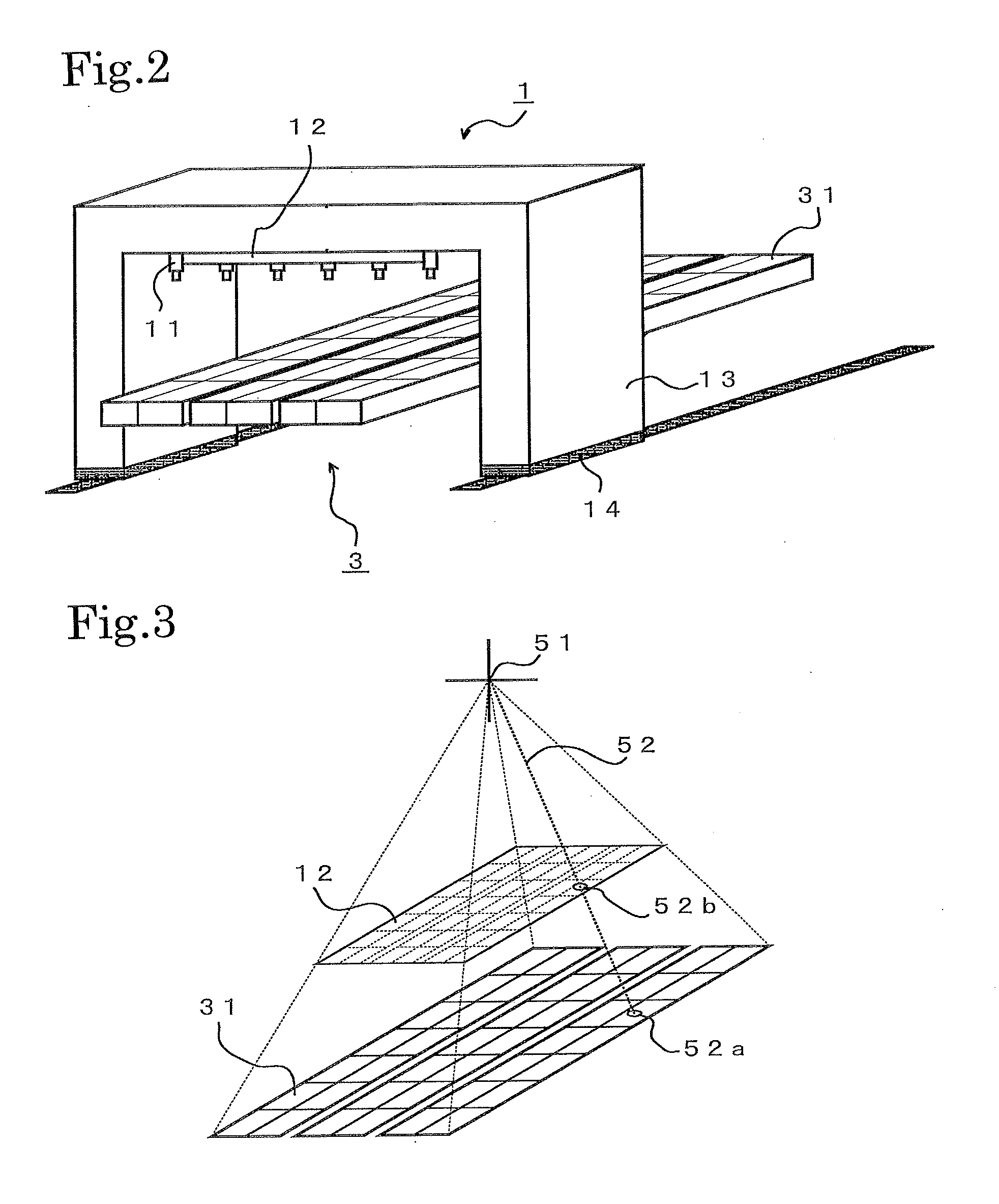
[0060]In a method of measuring the mounting postures of the respective facets 31, laser beams are emitted from the laser distance measuring unit 15, and distances from the arbitrarily-established reference line 54 to each facet 31 is thus measured.

[0061]In this respect, in each heliostat 3 for condensing rays of sunlight, the angle of each facet 31 is adjusted i...


PUM


Abstract

For work in which reflecting mirrors (or facets (31)) to be mounted on a heliostat 3 coincide with a pseudo toroid (53), an adjustment method of, and a mounting posture measuring device for, accurately measuring mounting postures of the respective facets (31) are provided for performing mounting adjustment efficiently and simply. In a method of installing the reflecting mirrors (or the facets (31)) constituting the heliostat 3 for sunlight condensation, each facet (31) is installed in such so that a reflected laser beam (52) reflected by the facet 31 can reach a virtual passage point (52b) in a laser point measuring unit (12).

Description

TECHNICAL FIELD[0001]The present invention relates to a device for measuring mounting postures of the respective reflecting mirrors (facets) which constitute heliostats for condensing rays of sunlight.BACKGROUND ART[0002]In the field of solar thermal power generation and the like in which rays of sunlight are condensed and used as energy, a condensation rate of a heliostat 3 (a reflecting mirror) for condensing rays of sunlight is raised by use of a mirror having a concave surface. It is desirable that this concave surface should be formed in three-dimensions with a toroid included therein. A durable mirror having a concave surface has been proposed (see Patent Document 1, for instance).[0003]However, its manufacturing costs are high. In addition, it is difficult to secure the manufacturing accuracy, and to manufacture the mirror in a large size. For this reason, used is a heliostat including small-sized and flat reflecting mirrors (facets 31) made coincide with a toroid 53 in a pse...

Claims


Application Information

Patent Timeline
IPC IPC(8): G02B5/10F24S50/20F24S23/77
CPCF24J2/16F24J2/542Y02E10/47G02B7/183G02B27/62F24J2002/1076F24S23/77F24S30/452F24S2023/87F24S50/20G05D3/12
Inventor EZAWA, KAZUAKIFUJIWARA, KAZUMASA
Owner MITSUI ENG & SHIPBUILD CO LTD
Why Eureka
Try Eureka