
Ringback replacement insertion system

a replacement insertion and ringback technology, applied in the field of customizing the communication network, can solve the problems of arising user interfaces for enabling the functionality of applications, the number of unused idle time of callers, and the almost limitless application of replacement ringback tones and announcements in the marketing industry

Inactive Publication Date: 2011-09-29
ECLIPS
View PDF2 Cites 17 Cited by
  • Summary
  • Abstract
  • Description
  • Claims
  • Application Information

AI Technical Summary

Benefits of technology

"The invention is a system that allows users to replace the ringback content on their phones with new content, such as music, video, or advertisements. The system can access the user's phone or a network service provider's system to select the desired ringback content. Users can also modify the current network addresses or telephone numbers associated with their phones by adding new ringback content. The system can also determine the physical location of the user's phone and use that information to select relevant content. Overall, the invention provides users with greater flexibility and customization options for their phone's ringback content."

Problems solved by technology

In addition, replacement ringback tones and announcements offer almost limitless applications in the marketing industry.
Typically, a caller experiences a rather large amount of unused idle time when waiting for a called party to answer his or her telephone.
As the adoption of the technology identified in the above-referenced application is emerging, certain drawbacks in the user interface for enabling the functionality of the application are arising.
This often inconvenient and time-consuming method of updating or adding new ringback content to a user's service discourages subscribers of a ringback replacement service from frequently modifying or adding new ringback replacement associations, thus reducing potential revenue by deterring regular and repeated ringback content purchasing and utilization.

Method used


Image

  • Ringback replacement insertion system
  • Ringback replacement insertion system
  • Ringback replacement insertion system

Examples


Embodiment Construction

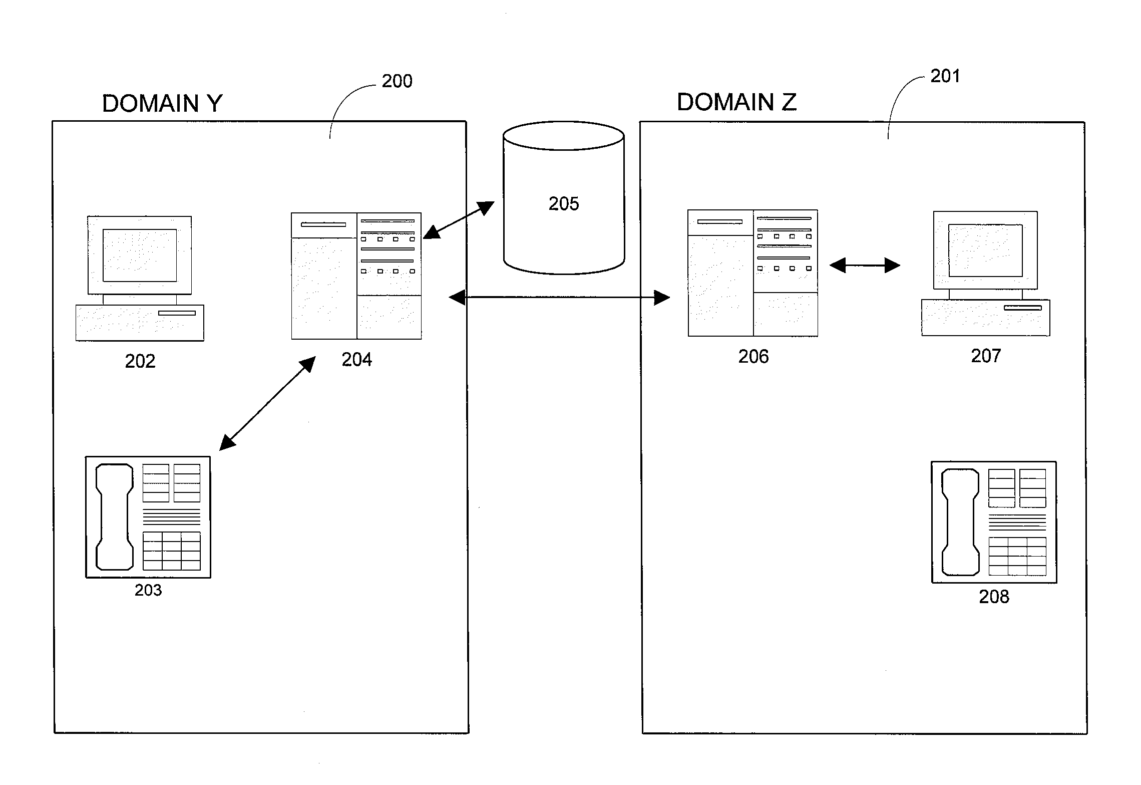
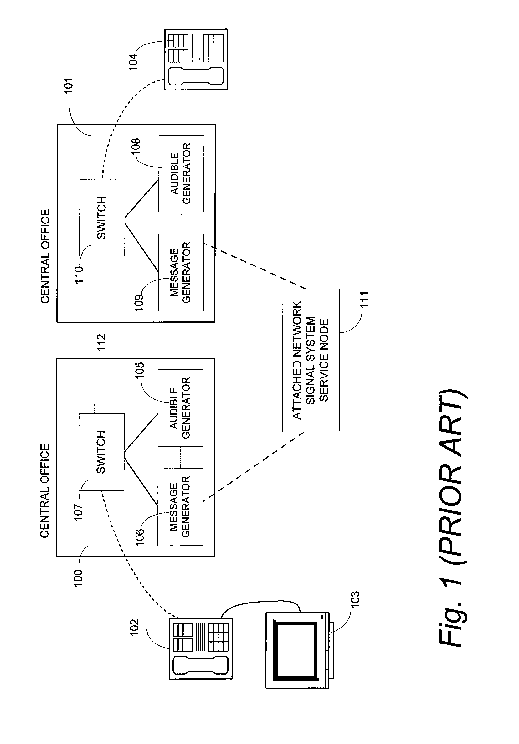
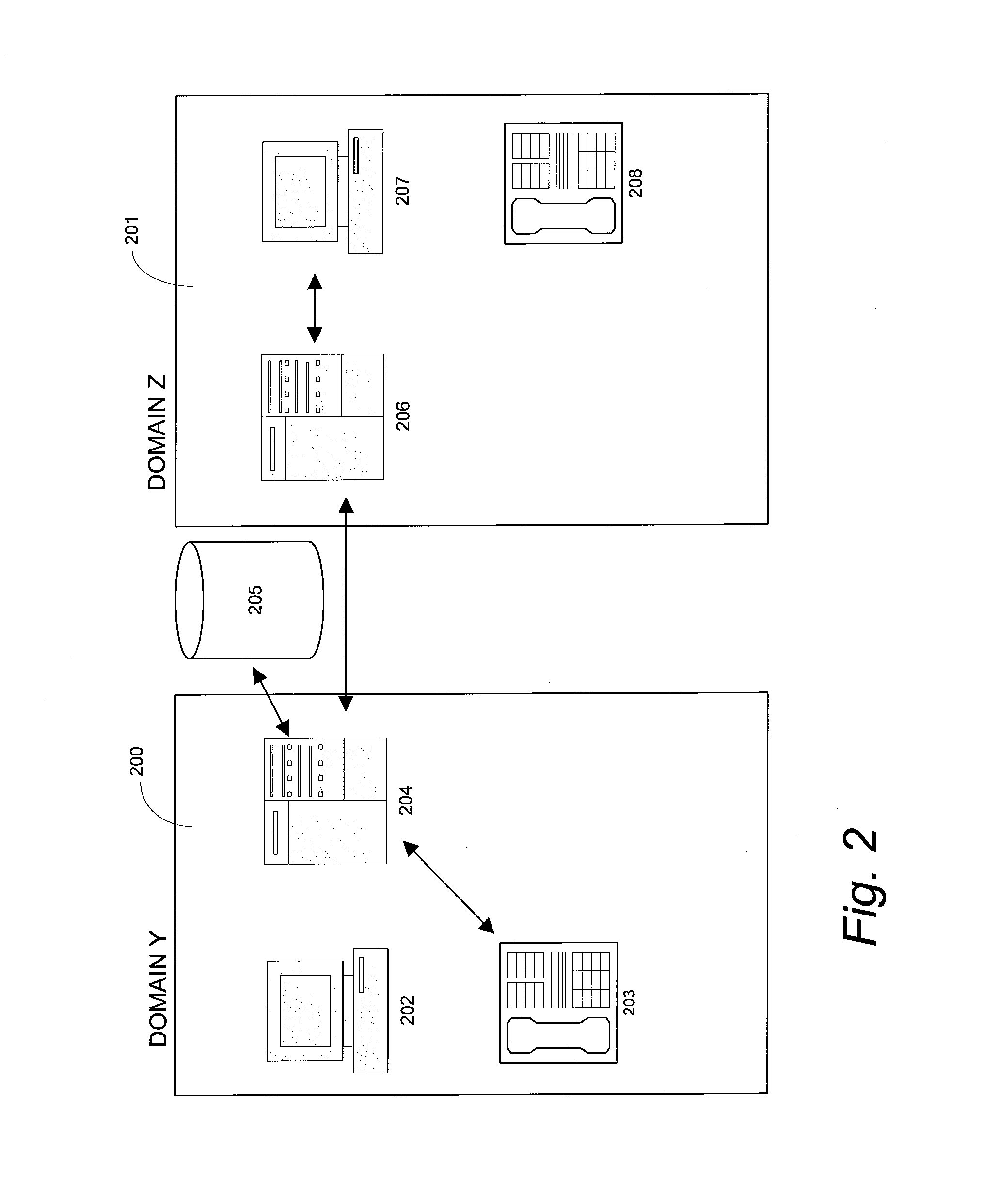
[0033]As required, a detailed illustrative embodiment of the invention is disclosed herein. However, techniques, systems, and operating structures in accordance with the invention may be embodied in a wide variety of forms and modes, some of which may be quite different from those in the disclosed embodiment. Consequently, the specific structural and functional details disclosed herein are merely representative, yet in that regard, they are deemed to afford the best embodiment for the purposes of disclosure and to provide a basis for the claims herein, which define the scope of the invention. The following presents a detailed description of a preferred embodiment (as well as some alternative embodiments) of the invention.

[0034]Referring to the drawings wherein like numerals indicate like elements throughout, there is shown in FIG. 1 (PRIOR ART) a conventional network-originated system for supplying replacement ringback content in accordance with a typical ringback control system. As...


PUM


Abstract

A ringback replacement insertion system for customizing a communication network is disclosed. The system includes a first communication station associated with a first network service provider and a second communication station associated with a second network service provider. A network gateway is provided for connecting a call placed from the first communication station to the second communication station. The first network service provider receives information regarding a proximity location of the first communication station. The storage device transmits at least a portion of the at least one announcement to the first communication station that is related to information within a predefined geographical distance from the first communication station, where at least a portion of the at least one announcement is delivered as a call signal after establishing contact with a communication network.

Description

CROSS-REFERENCE TO RELATED APPLICATIONS [0001]This continuation-in-part application claims the benefit of copending Non-Provisional application Ser. No. 11 / 137,143, filed May 25, 2005, the entire contents of which is herein incorporated by reference.FIELD OF THE INVENTION [0002]The invention relates generally to the customization of a communications network and, more particularly, to the customization of a communications network including replacement ringback announcements and the system for inserting replacement ringback content within a network or multi-carrier network.BACKGROUND OF THE INVENTION [0003]Most conventional communications networks today, particularly existing telephone networks, provide a calling party with an audible ringback signal when an intended called network address or station line is idle and a busy signal when the intended called network address or station line is already in use (i.e., the telephone or other device at the called network address is being used)...

Claims


Application Information

Patent Timeline
Patent Type & Authority Applications(United States)
IPC IPC(8): H04M3/42
CPCH04M3/42017H04M3/42068H04M2242/15H04M3/4878H04M3/42153
Inventor RADZIEWICZ, CLIFFORD J.GREGOREK, MARK K.DILLOW, JEFFREY C.
Owner ECLIPS
Learn More