Device and process for three-dimensional localization and pose estimation using stereo image, and computer-readable storage medium storing the program thereof

a three-dimensional localization and pose technology, applied in image enhancement, image analysis, instruments, etc., can solve the problems of stereo method having a long-held problem called “occlusion”, measuring incorrect localization and pose, and failing to recognize the target object, etc., to achieve accurate localization and pose estimation, accurate localization and pose recognition

Inactive Publication Date: 2011-09-29
NAT INST OF ADVANCED IND SCI & TECH +1
View PDF13 Cites 47 Cited by
  • Summary
  • Abstract
  • Description
  • Claims
  • Application Information

AI Technical Summary

Benefits of technology

[0048]The present invention enables accurate localization and pose estimation without influence of a three-dimensional reconstructed structure generated by false stereo correspondence that may occur in a portion of image data due to occlusion or the like. In the conventional method that supplementarily uses an additional camera image for verification, there are some cases where a correct combination of stereo correspondence is regarded as false correspond

Problems solved by technology

This function cannot be achieved by other image processing techniques.
On the other hand, the stereo method has a long-held problem called “occlusion”, which occurs due to the positional difference between the cameras.
When the three-dimensional reconstruction is performed with an image set having occlusion, a stereo correspondence error occurs in the defective part, thereby failing the recognition of the target object, or measuring incorrect localization and pose due to the resulting false th

Method used


Image

  • Device and process for three-dimensional localization and pose estimation using stereo image, and computer-readable storage medium storing the program thereof
  • Device and process for three-dimensional localization and pose estimation using stereo image, and computer-readable storage medium storing the program thereof
  • Device and process for three-dimensional localization and pose estimation using stereo image, and computer-readable storage medium storing the program thereof

Examples


examples

[0124]Examples of the present invention are described below to further clarify the effectiveness of the present invention.

first example

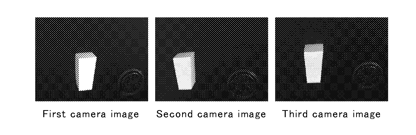
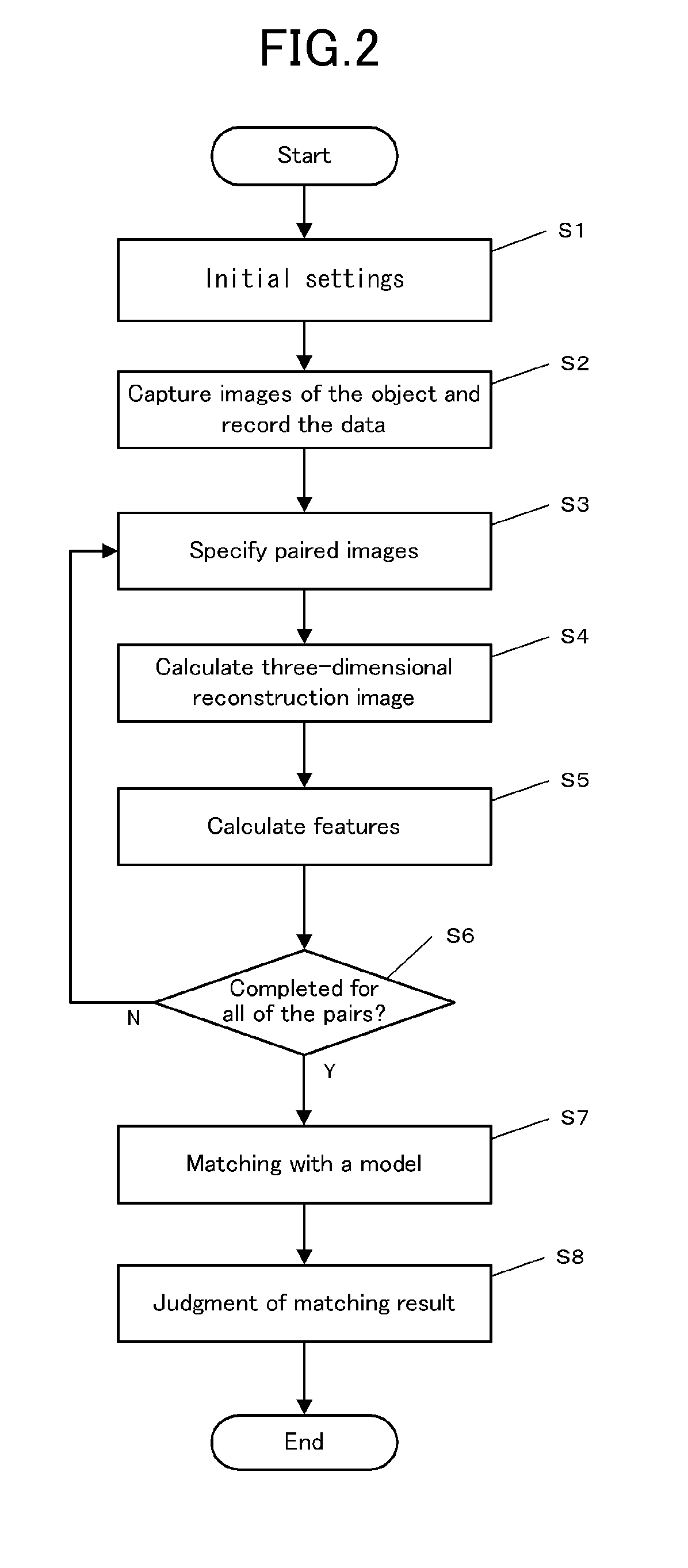
[0125]In First Example, to more easily understand the condition of false stereo correspondence, the measurement was performed using a model having a simple shape. An image of the object shown in FIG. 5 was captured using three cameras as the first to third imaging units, and the obtained image data was processed according to the flow chart shown in FIG. 2.

[0126]The three cameras were arranged such that the second camera was disposed on the right of the first camera with a base length of 25 cm, and the third camera was disposed upward from the center of the first and second cameras at a 6 cm distance.

[0127]As an appropriate target object shown in FIG. 5 to more clearly show the condition of false stereo correspondence, an object having a simple shape, namely, a 40 mm (width)×40 mm (depth)×78 mm (height) rectangular solid with one inclined side was used. The trapezoid shown in the front view has an upper width of 40 mm and a lower width of 30 mm. The rectangular solid was not a comple...

second example

[0136]In First Example, a model having a simple shape was used to more clearly show the condition of false stereo correspondence. For comparison, another experiment was performed using an object having a more complicated shape. The result of this experiment is explained below as Second Example. In Second Example, the measurement was performed using an L-shaped object as a target object, which is a shape closer to a real industrial component, and a structure simple enough to be drawn on a diagram. The L-shaped object had two L-shaped faces and six rectangular faces.

[0137]FIG. 16 is a perspective view showing the shape of the model used in Second Example. The arrows labeled as x, y, z in the vicinity of the center of the model show axes of the model-coordinate system, and “o” indicates its origin. The six arrows with labels (a) to (f) indicate respective viewpoints in each figure of FIGS. 19 and 21 showing the results of the matching experiments.

[0138]FIG. 17 shows trinocular stereo p...


PUM


Abstract

The device includes:
    • an input unit (4) for receiving image data obtained by capturing images of an object by imaging units (C1 to C3); and
    • an arithmetic unit (1) that performs:
    • 1) finding a three-dimensional reconstruction point set that contain three-dimensional position information of segments obtained by dividing a boundary of the object in the image data, and a feature set that contain three-dimensional information regarding vertices of the segments, for each of multiple pairs of two different images;
    • 2) calculating a total three-dimensional reconstruction point set and a total feature set by totaling the three-dimensional reconstruction point sets and the feature sets of the multiple pairs; and
    • 3) matching a model feature set regarding model data of the object with the total feature set, thereby determining, among the total three-dimensional reconstruction point set, points corresponding to model points of the object.

Description

TECHNICAL FIELD[0001]The present invention relates to a device and a process for carrying out three-dimensional localization and pose estimation of an object using images of the object captured by a plurality of cameras; and a computer-readable storage medium storing the program thereof.BACKGROUND ART[0002]The stereo method is a technique for reconstructing a three-dimensional environment using images captured by a plurality of cameras at different viewpoints. In recent years, the image recognition technique has become more frequently used in the factory automation field. Particularly, among them, the stereo method has a function of measuring a three-dimensional shape, size, localization and pose of the target object with high accuracy. This function cannot be achieved by other image processing techniques. With this advantage, the stereo method is widely applicable in the industrial field; for example, for manipulation of robots for bin-picking of randomly placed parts. Moreover, th...

Claims


Application Information

Patent Timeline
IPC IPC(8): G06K9/00
CPCG06K9/00214G06T2207/10016G06T7/0046G06T7/75G06V20/653
Inventor WATANABE, MASAHARUTOMITA, FUMIAKIFUJIMURA, KOUTAIKEDA, YASUYUKIICHIMURA, KENGO
Owner NAT INST OF ADVANCED IND SCI & TECH
Why Eureka
Try Eureka