Method for positron emission mammography image reconstruction
- Summary
- Abstract
- Description
- Claims
- Application Information
AI Technical Summary
Benefits of technology
Problems solved by technology
Method used
Image
Examples
example 1
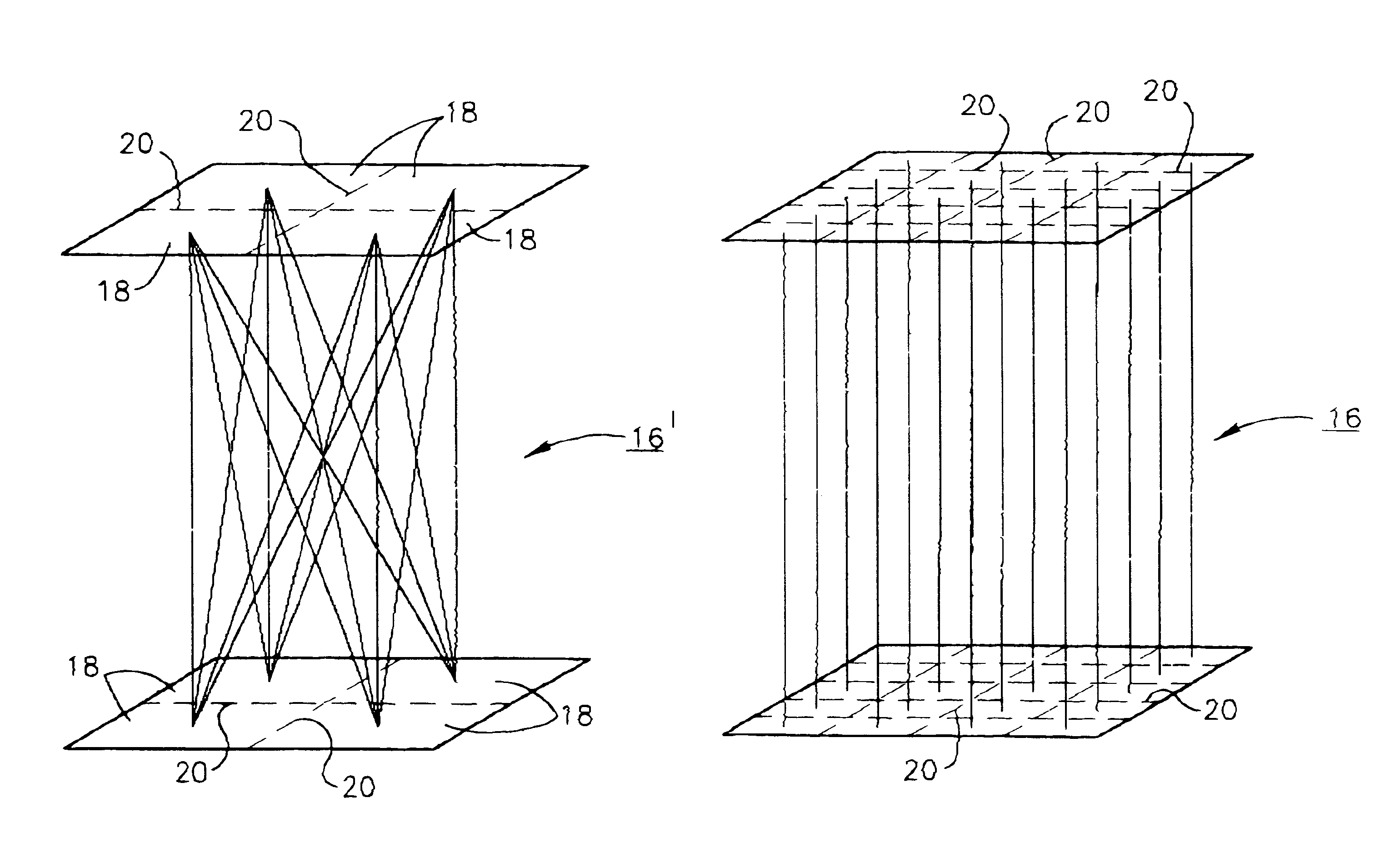
Reconstructions using the foregoing parameters and comparing the conventional backprojection formulae FIGS. 6 and 7 and those of the present invention are compared in FIGS. 8 and 9. In studying the results depicted in FIGS. 6 and 7, note should be taken of the banding and artifacts and that the contrast of small lesions is improved with smaller reconstruction pixels. In FIG. 8, the elimination of banding and pixelization artifacts should be noted. In FIG. 9, note should be taken of the improved uniformity over the field of view with any remaining image non-uniformities being due to intrinsic detector factors or to source distribution effects.
example 2
Iterative MLEM formulae, 3.3 mm pixels, 1 ray / TOR results are depicted in FIG. 10. In these examples, lesion contrast is improved compared with backprojection reconstruction, at the expense of some additional image noise. A discontinuity is visible at the midline of the coronal slice.
example 3
Iterative MLEM formulae, 1.65 mm pixels, 1 ray / TOR results are depicted in FIG. 11. The high frequency content of the images is slightly improved by the use of smaller pixels, at the expense of lower signal-to-noise ratio. A discontinuity is visible at the midline of the coronal slice.
PUM
 Abstract
Description
Claims
Application Information
 - R&D
- Intellectual Property
- Life Sciences
- Materials
- Tech Scout
- Unparalleled Data Quality
- Higher Quality Content
- 60% Fewer Hallucinations
Browse by: Latest US Patents, China's latest patents, Technical Efficacy Thesaurus, Application Domain, Technology Topic, Popular Technical Reports.
© 2025 PatSnap. All rights reserved.Legal|Privacy policy|Modern Slavery Act Transparency Statement|Sitemap|About US| Contact US: help@patsnap.com


