
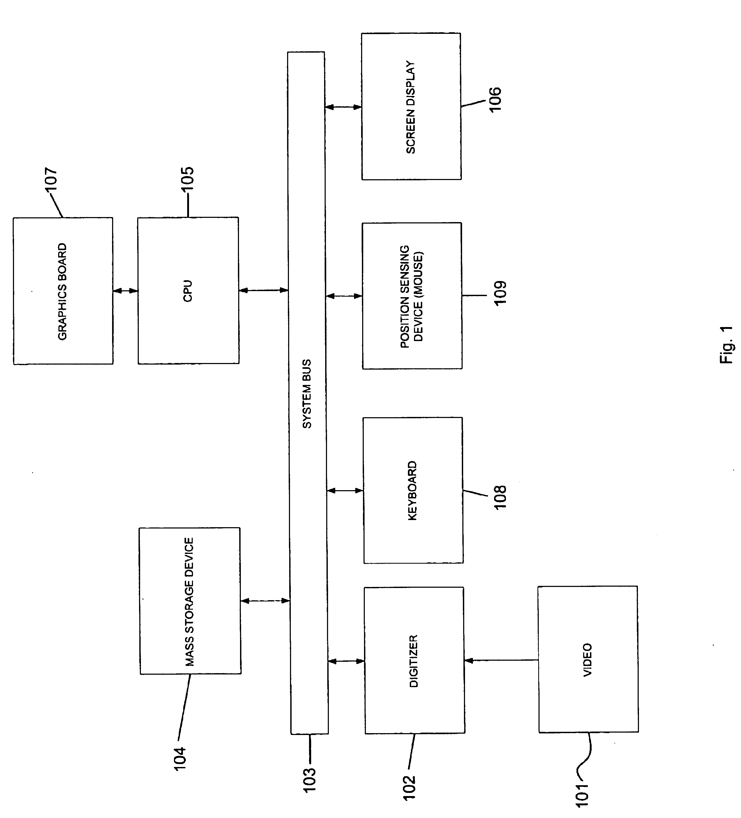
Method for recovering 3D scene structure and camera motion from points, lines and/or directly from the image intensities

Inactive Publication Date: 2005-02-22
NEC CORP
View PDF1 Cites 63 Cited by
  • Summary
  • Abstract
  • Description
  • Claims
  • Application Information

AI Technical Summary

Benefits of technology

The method of the invention is a general motion algorithm wherein the camera positions for each successive perspective do not lie on a single plane. The method can reconstruct the image from points, lines or intensities.
The method of the present invention can reconstruct from both point and line features. This is an important aspect of the present invention, since straight lines are abundant, especially in human-made environments, and it is often possible to track both feature types. Lines can be localized very accurately due to the possibility of finding many sample points on a single line, and they do not suffer from some of the problems of point tracking such as spurious T-junctions and the aperture effect. The method described here is the first that can reconstruct from all three types of input data in any combination or separately over a sequence of arbitrarily many images under full perspective.

Problems solved by technology

However, in practice, it is sometimes necessary to impose smoothness in the algorithm.

Method used


Image

  • Method for recovering 3D scene structure and camera motion from points, lines and/or directly from the image intensities
  • Method for recovering 3D scene structure and camera motion from points, lines and/or directly from the image intensities
  • Method for recovering 3D scene structure and camera motion from points, lines and/or directly from the image intensities

Examples


Embodiment Construction

Definitions

For purposes of this disclosure, the invention will be described in accordance with the following terms defined herein. The method of the present invention assumes that the calibration is known and takes the focal length to be 1 (wlog). Modifications to the method for uncalibrated sequences will be discussed later.

Assuming a sequence of Ni images. Choose the zeroth image as the reference image. Let Ri, Ti denote the rotation and translation between this image and image i. Parameterize small rotations by the rotational velocity ω≡(ωxi,ωyi,ωzi)T. Let [Ti]2≡(TxiTyi)T.

Let a 3D point P transform as P′=R(P−T). Assume Np points and NL lines tracked over the sequence. For clarity, we use a different notation for the tracked points than for the pixel positions in the intensity images. Let qmi≡(qx,qy)mi denote the m-th tracked point and Ali≡(α,β,γ)lTi denote the i-th line in the i-th image. Let {overscore (q)}≡(q;1)T. Let R*q denote the image point obtained from q after a rotation:...


PUM


Abstract

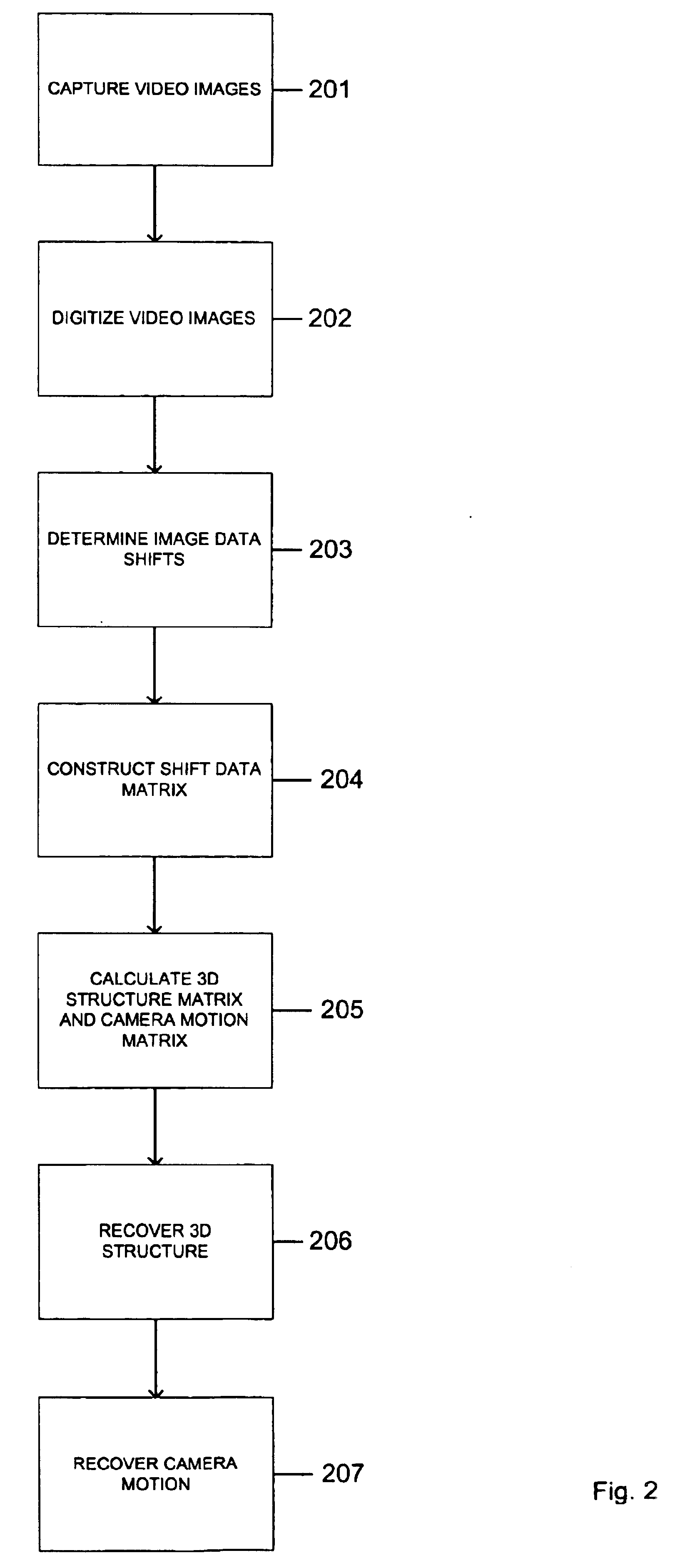
An algorithm for recovering structure and motion from points, lines and / or image intensities. The algorithm combines feature based reconstruction and direct methods. The present invention is directed to a method for recovering 3D scene structure and camera motion from image data obtained from a multi-image sequence, wherein a reference image of the sequence is taken by a camera at a reference perspective and one or more successive images of the sequence are taken at one or more successive different perspectives by translating and / or rotating the camera. The method comprising the steps of (a) determining image data shifts for each successive image with respect to the reference image; the shifts being derived from the camera translation and / or rotation from the reference perspective to the successive different perspectives; (b) constructing a shift data matrix that incorporates the image data shifts for each image; (c) calculating two rank-3 factor matrices from the shift data matrix using SVD, one rank-3 factor matrix corresponding the 3D structure and the other rank-3 factor matrix corresponding the camera motion; (d) recovering the 3D structure from the 3D structure matrix using SVD by solving a linear equation; and (e) recovering the camera motion from the camera motion matrix using the recovered 3D structure.

Description

BACKGROUND OF THE INVENTION1. Field of the InventionThe present invention is directed to a method for recovering 3D structure and camera motion, and more particularly to a linear algorithm for recovering the structure and motion data from points, lines, and / or directly from the image intensities.2. Prior ArtThe science of rendering a 3D model from information derived from a 2D image predates computer graphics, having its roots in the fields of photogrammetry and computer vision.Photogrammetry is based on the basic idea that when a picture is taken, the 3D world is projected in perspective onto a flat 2D image plane. As a result, a feature in the 2D image seen at a particular point actually lies along a particular ray beginning at the camera and extending out to infinity. By viewing the same feature in two different photographs the actual location can be resolved by constraining the feature to lie on the intersection of two rays. This process is known as triangulation. Using this pro...

Claims


Application Information

Patent Timeline
IPC IPC(8): G01B11/24G01B11/00G06K9/00G06K9/32G06T1/00G06T7/20H04N7/18G06T7/00G06V10/147
CPCG06K9/209G06T7/2033G06T7/0071G06K2209/40G06T7/579G06T7/246G06V10/147G06V2201/12
Inventor OLIENSIS, JOHN
Owner NEC CORP
Learn More