Optical element and lighting apparatus

A technology for optical components and lighting equipment, applied in the field of lighting equipment and searchlights, can solve the problems of large structure space, easy interference, high cost, etc., and achieve the effects of accurate positioning, high refraction value, and simple manufacturing

Inactive Publication Date: 2018-01-30
OSRAM GMBH
View PDF6 Cites 4 Cited by
  • Summary
  • Abstract
  • Description
  • Claims
  • Application Information

AI Technical Summary

Problems solved by technology

The two parts are provided by different optical systems, which represents a high cost and component outlay
Furthermore, such different optical systems typically require a large amount of installation space and are susceptible to disturbances with respect to external influences such as vibrations

Method used


Image

  • Optical element and lighting apparatus
  • Optical element and lighting apparatus

Examples


Embodiment Construction

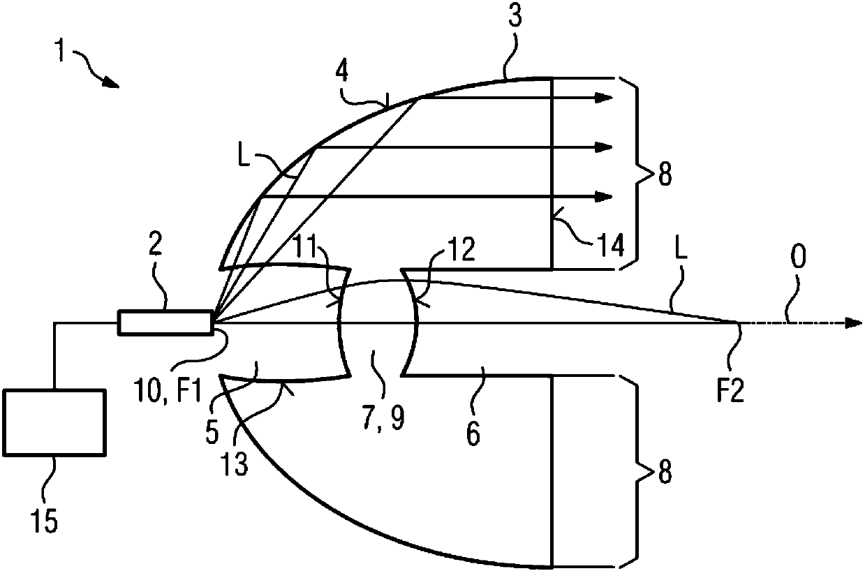
[0067] figure 1 A lighting device 1 with a light generating device 2 and an optical element 3 is shown.

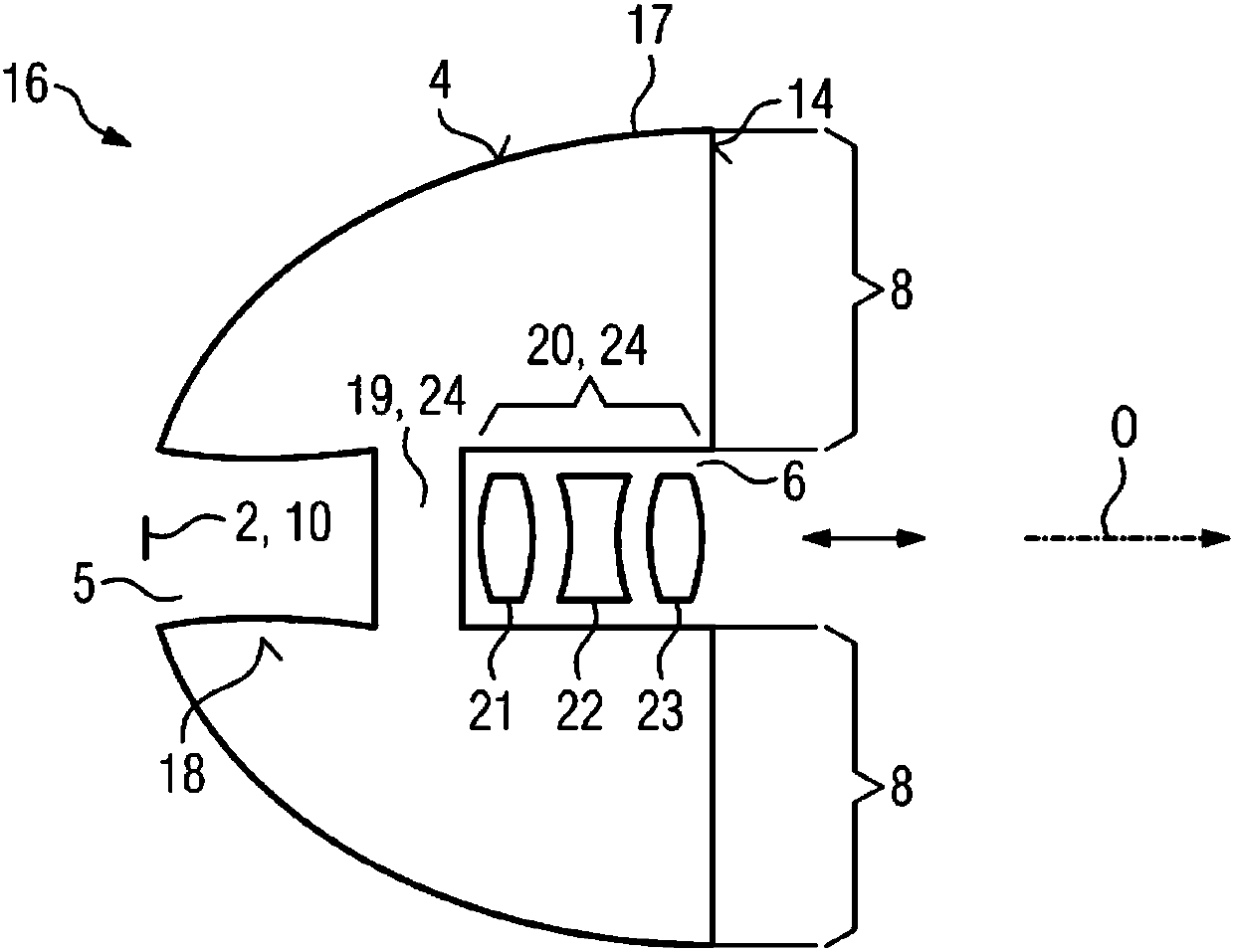
[0068] The optical element 3 is a one-piece, transparent body, for example of plastic or glass. The body has, for example, a parabolic or free-surface-shaped outer casing 4 , which expands forward along the axis O here.

[0069] The optical element 3 has a rear recess 5 introduced centrally with respect to the axis O and a front recess 6 introduced centrally with respect to the axis O. The two recesses 5 and 6 are separated from one another by a lenticularly shaped partition wall 7 . The lenticular partition 7 forms the lens arrangement of the imaging region 9 of the optical element 3 , while the region of the optical element 3 surrounding the lenticular partition 7 laterally and circumferentially forms the collimation region 8 . Since the lenticular partition 7 here represents the only lens of the lens arrangement, the lenticular partition 7 corresponds to the imaging ...


PUM


Abstract

An optical element (3) includes an imaging region (9) with a lens arrangement (7) which is aligned along an optical axis (O), and a collimation region (8) which surrounds the imaging region (9) to theside of the optical axis (O). A lighting apparatus (1) includes an optical element (3) as described above and a light-producing device (2) for simultaneously illuminating the collimation region (8) and the imaging region (9) of the optical element (3), wherein the lens arrangement (7) is adjustable by mechanical means for the purposes of varying the optical property thereof and/or the light-producing device (2) is configured to locally vary light density distribution of the light emitted thereby. Various embodiments are applicable, for example, to projectors, e.g. for vehicles, stage and effect lighting, external lighting, etc.

Description

technical field [0001] The invention relates to an optical element having an imaging region with a lens arrangement oriented along an optical axis. The invention also relates to a lighting device having such an optical element. The invention can be used, for example, in searchlights for vehicles, stage lighting and effect lighting, outdoor lighting and the like. Background technique [0002] In principle, optical elements are known which have a lens arrangement arranged along an optical axis. Optically transparent elements are also known in principle, which are used as collimators. [0003] Headlight systems are known from automotive technology, in which a light distribution or a light emission pattern is produced by a plurality of light sources, for example by a plurality of LEDs arranged in series and / or as a two-dimensional matrix. [0004] Floodlight systems are known in the prior art, in which a plurality of individually switchable light sources (usually LEDs) are us...

Claims


Application Information

Patent Timeline
Patent Type & Authority Applications(China)
IPC IPC(8): F21V5/04G02B3/00F21S8/00
CPCF21S41/143F21S41/24F21S41/255F21S41/265F21S41/322F21S41/663F21S41/153G02B27/0927G02B27/0955G02B27/0068G02B27/30H01S3/005
Inventor 斯特凡·施魏格尔于尔根·黑格
Owner OSRAM GMBH
Why Eureka
Try Eureka