
Bed-type circular saw blade grinder

a circular saw blade and grinder technology, applied in the field of grinding technique of saw blades, can solve the problems of unfavorable processing quality, unfavorable use, and inability to meet the needs of customers, and achieve the effects of convenient manufacture, reduced cost, and simplified structur

Inactive Publication Date: 2011-09-29
CHANG TUNG MIN
View PDF20 Cites 19 Cited by
  • Summary
  • Abstract
  • Description
  • Claims
  • Application Information

AI Technical Summary

Benefits of technology

The present invention is a bed-type circular saw blade grinder that has a simplified structure and is easy to manufacture at lower cost. It can be more conveniently used with the possibility of failure minimized. The grinder includes a bed section, a support section, a rotary seat, a circular saw blade restriction section, and a grinding unit. The grinding unit has a grinding piece for grinding saw teeth of the circular saw blade. The grinding piece is positioned to grind the saw tooth when the rotary seat is in the first position and to space from the saw tooth when the rotary seat is in the second position. The grinding unit is driven by the rotary seat to move with it when the rotary seat is pivotally rotated between the first and second positions. The technical effect of the present invention is to provide a convenient and cost-effective tool for grinding circular saw blades.

Problems solved by technology

After a period of use, the circular saw blade will be inevitably worn out to affect the processing quality.
The above circular saw blade grinder has a complicated structure and is uneasy to use.

Method used


Image

  • Bed-type circular saw blade grinder
  • Bed-type circular saw blade grinder
  • Bed-type circular saw blade grinder

Examples


Embodiment Construction

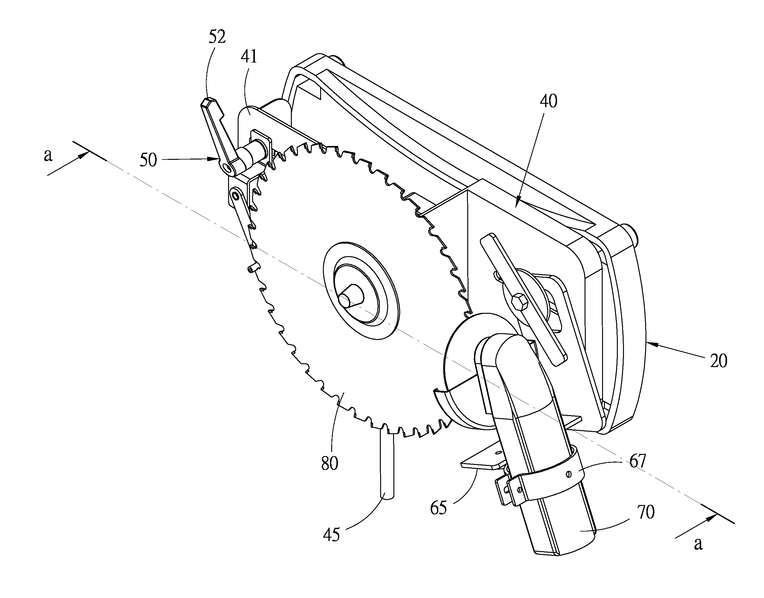
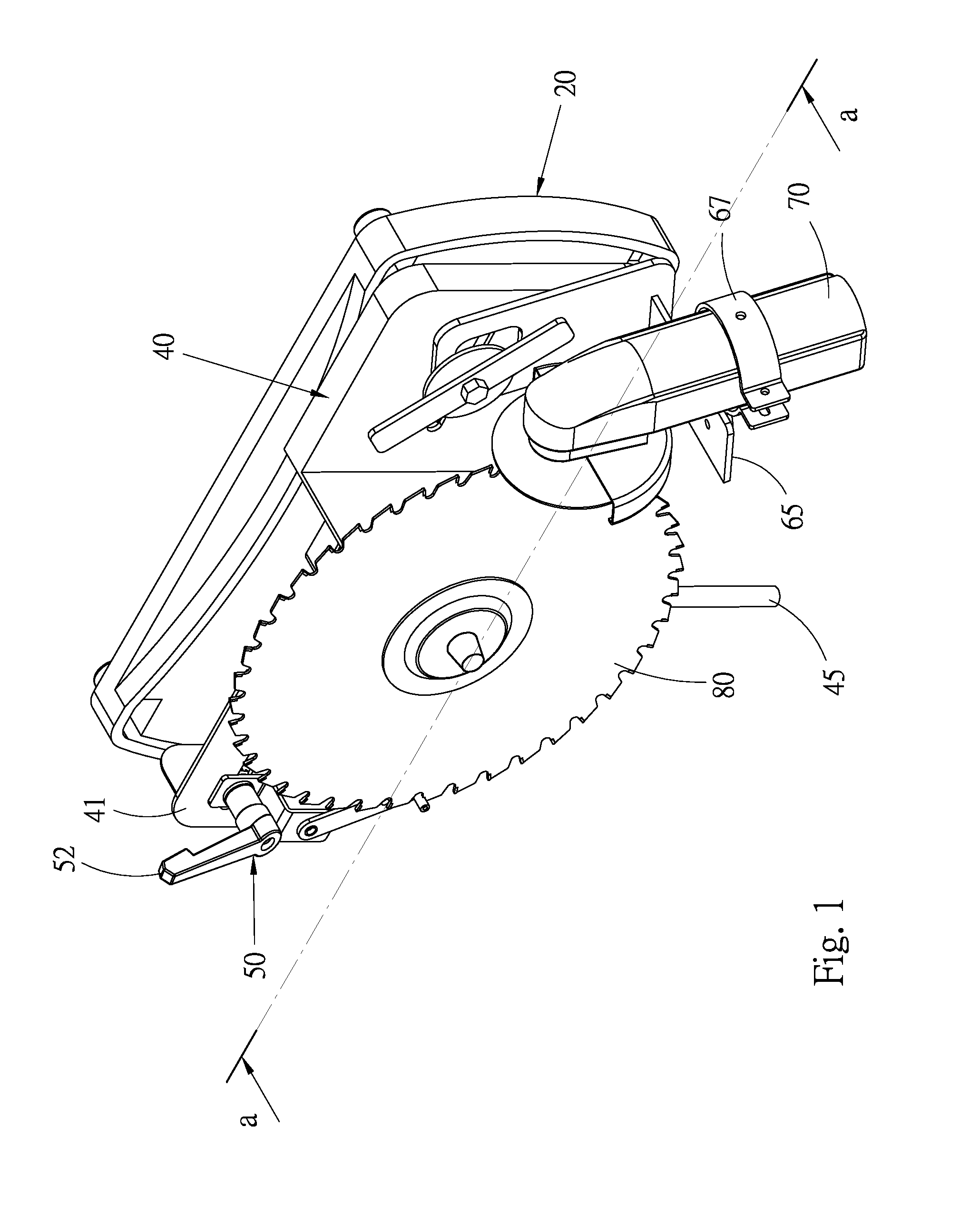
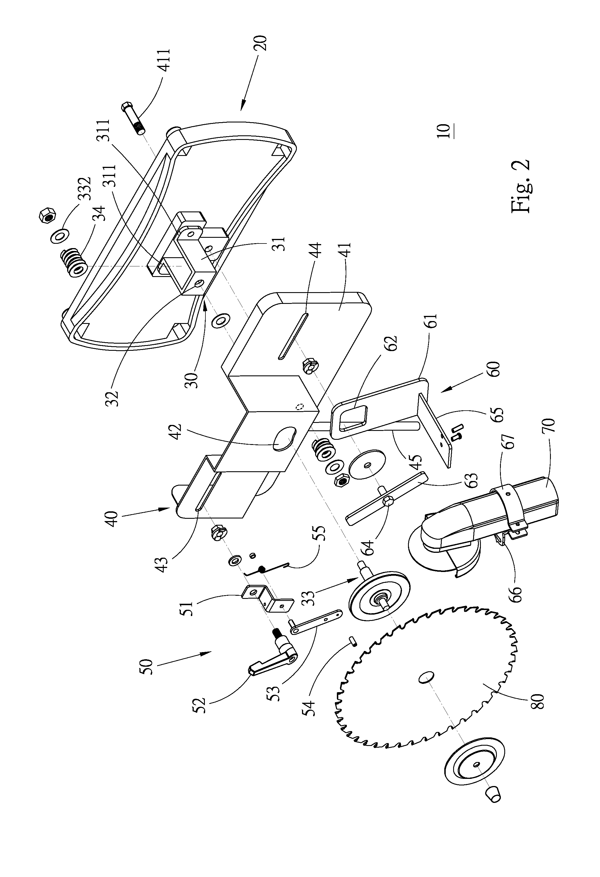
[0018]Please refer to FIGS. 1 to 9. According to a preferred embodiment, the bed-type circular saw blade grinder 10 of the present invention includes a bed section 20, a support section 30, a rotary seat 40, a circular saw blade restriction section 50, a grinding unit retainer seat 60 and a grinding unit 70.

[0019]The bed section 20 is a board body with a certain weight as a base on which the other components of the bed-type circular saw blade grinder 10 are mounted. The bed section 20 also helps in stabilizing the operation of the bed-type circular saw blade grinder 10.

[0020]The support section 30 has a substantially U-shaped support body 31 with a certain height. Two wing plates 311 laterally extend from bottom ends of two sides of the support body 31. The wing plates 311 are attached to and fixedly connected with an upper face of the bed section 20. A top wall of the support body is formed with a shaft hole 32. The shaft hole 32 has an axis normal to the upper face of the bed sect...


PUM

PropertyMeasurementUnit
heightaaaaaaaaaa
frictional forceaaaaaaaaaa
diameteraaaaaaaaaa

Abstract

A bed-type circular saw blade grinder includes: a bed section; a support section fixedly connected with the bed section, a circular saw blade being rotatably connected with the support section; a rotary seat pivotally disposed on the bed section via a pivot shaft and reciprocally rotatable about the pivot shaft between a first position and a second position, the rotary seat having a first connection section and a second connection section positioned on two sides of the pivot shaft; a circular saw blade restriction section disposed at the first connection section for driving the circular saw blade to intermittently rotate; and a grinding unit disposed at the second connection section for grinding saw teeth. When the rotary seat is pivotally rotated between the first and second positions, the rotary seat drives the circular saw blade restriction section and the grinding unit to move with the rotary seat.

Description

BACKGROUND OF THE INVENTION[0001]1. Field of the Invention[0002]The present invention relates generally to a grinding technique for saw blade, and more particularly to a bed-type circular saw blade grinder.[0003]2. Description of the Related Art[0004]A circular saw is widely used in various fields such as machining and carpentry for sawing and processing a work piece. After a period of use, the circular saw blade will be inevitably worn out to affect the processing quality. Under such circumstance, it is necessary to grind the saw teeth of the circular saw blade and recover the sharpness of the saw teeth. Taiwanese Patent Application No. 076201481 discloses a grinder specifically for a circular saw blade. The grinder is characterized in that an electromagnetic retainer is used to retain a circular saw blade to be ground. A mechanical claw is used to control the pitch between the ground saw teeth. An advanced grinding motor transmission mechanism is used to drive a universally adjust...

Claims


Application Information

Patent Timeline
Patent Type & Authority Applications(United States)
IPC IPC(8): B24B3/46
CPCB23D63/005B24B3/46B23D63/14
Inventor CHANG, TUNG-MIN
Owner CHANG TUNG MIN
Learn More