Automatic transmission for a hybrid vehicle

Active Publication Date: 2011-09-29
BORG WARNER INC
View PDF192 Cites 16 Cited by
  • Summary
  • Abstract
  • Description
  • Claims
  • Application Information

AI Technical Summary

Benefits of technology

[0011]In this way, and under certain predetermined conditions, both the first and second pumps are operable to supply pressurized fluid to the hydraulic circuit when necessary. This may occur, for example, when the pressure delivered to the cooling circuit drops below a predetermined value. In this case, the second pump driven by the electric motor assists the first pump to provide cooling fluid to the cooling circuit when the first check valve is open. This arrangement allows the use of a smaller capacity, mechanically driven first pump and thereby reduces the cost of the transmission.

Problems solved by technology

Controlling and regulating transmissions to achieve the desired vehicle occupant comfort goals in an efficient and cost effective manner is a complicated matter.
Since hydraulically actuated devices respond in a predetermined and a precise manner for the given pressure supplied to actuate them, inaccurate control of the hydraulic pressure causes inaccurate operation and control of the transmission.
Establishing and maintaining a stable hydraulic pressure in an automatic transmission can be problematic.
The challenges of maintaining hydraulic pressure delivered from the pump in a conventional vehicle are only complicated in a hybrid vehicle.
However, even when the electric motor drives the vehicle, the clutches, as well as other components of the transmission, still need to have access to pressurized transmission fluid.
This arrangement results in increased costs and complexity as the transmission must be configured to receive hydraulic fluid from two separate sources depending on which portion of the hybrid's power plant is operational.
In addition, there is a certain inefficiency in having two pumps that serve the same purpose but are alternatingly operable depending on the source of motive power used to drive the hybrid engine.

Method used


Image

  • Automatic transmission for a hybrid vehicle
  • Automatic transmission for a hybrid vehicle
  • Automatic transmission for a hybrid vehicle

Examples


Embodiment Construction

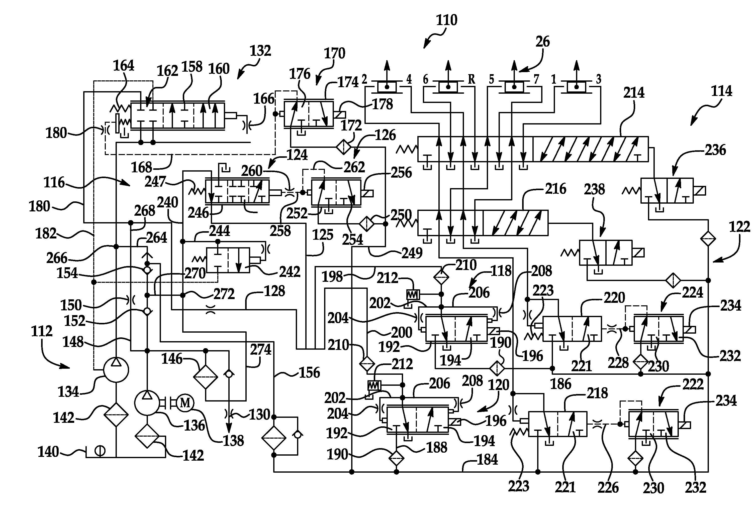
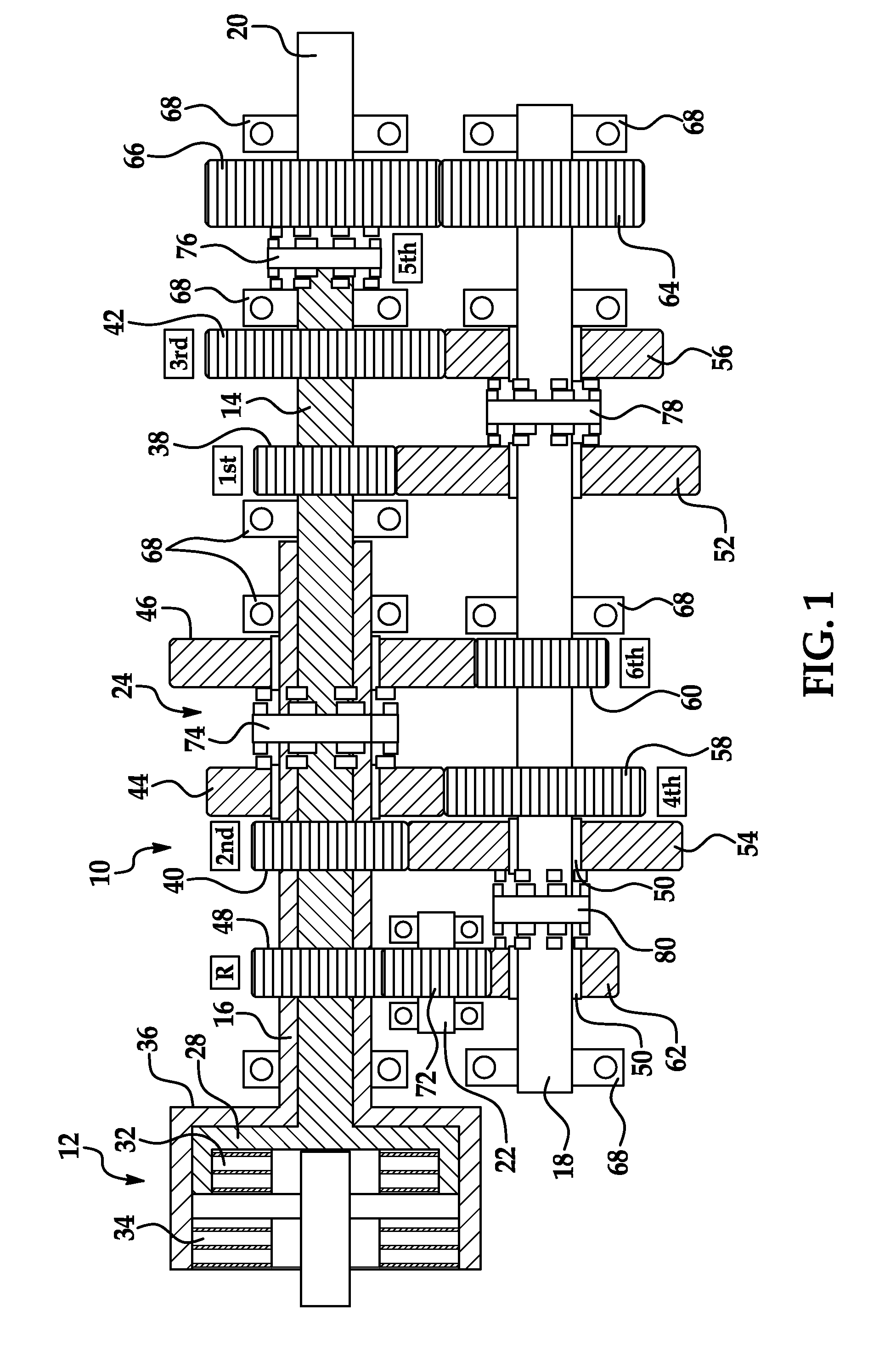
[0015]A representative example of an automatic transmission that may be employed for a hybrid engine is generally indicated at 10 in FIG. 1. In this case, the automatic transmission described and illustrated herein is a dual clutch transmission. However, those having ordinary skill in the art will appreciate from the description that follows that the present invention may be employed in connection with any type of automatic transmission used for a hybrid engine. Thus, those having ordinary skill in the art will understand that the present invention is defined by the claims set forth herein, rather than by the dual clutch transmission illustrated in FIG. 1 and described below. As illustrated in FIG. 1, the dual clutch transmission 10 may include a dual, coaxial clutch assembly generally indicated at 12, a first input shaft, generally indicated at 14, a second input shaft, generally indicated at 16, that is coaxial to the first, a counter shaft, generally indicated at 18, an output sh...


PUM


Abstract

An automatic transmission for a hybrid vehicle includes a hydraulic circuit (110) having a source of pressurized fluid (112), an actuation circuit (114) that delivers pressurized fluid to actuate components of the transmission, and a cooling circuit (116) used to cool components of the transmission. The source of pressurized fluid includes a first pump (134) that is operatively driven by the internal combustion engine of the hybrid vehicle and a second pump (136) that is operatively driven by the electric motor (138). The second pump (136) acts to supply pressurized fluid to the cooling circuit (116) when the first pump (134) is operatively driven by the internal combustion engine under certain predetermined conditions.

Description

BACKGROUND OF THE INVENTION[0001]1. Field of the Invention[0002]The present invention relates, generally, to an automatic transmission and, more specifically, to an automatic transmission designed for use with a hybrid vehicle.[0003]2. Description of the Related Art[0004]Generally speaking, land vehicles require a powertrain consisting of three basic components. These components include a power plant (such as an internal combustion engine), a power transmission, and wheels. The power transmission component is typically referred to simply as the “transmission.” Engine torque and speed are converted in the transmission in accordance with the tractive-power demand of the vehicle.[0005]Hybrid vehicles employ two separate power plants. One power plant is typically an internal combustion engine. The other is an electric motor. The electric motor is powered by electrical energy stored in a bank of batteries that are typically also supported on the vehicle. The batteries may be recharged by...

Claims


Application Information

Patent Timeline
IPC IPC(8): B60W10/10B60W20/00
CPCB60K6/36B60K6/48B60Y2400/428F16H57/0439Y10T477/23F16H61/0031F16H2061/0037Y02T10/6221Y10T477/26F16H57/0446Y02T10/62
Inventor KOENIG, MELISSAXIANG, XIAONING
Owner BORG WARNER INC
Why Eureka
Try Eureka