Physiological sensor device

a sensor device and physiological technology, applied in the field of single-use disposable physiological sensor devices, can solve the problems of high prone to detachment of electrodes, incomplete or inaccurate data collection, and spurious signals of electrodes, so as to improve reliability, accuracy and integrity of collected data

Inactive Publication Date: 2011-09-29
HALTHION MEDICAL TECH INC
View PDF29 Cites 190 Cited by
  • Summary
  • Abstract
  • Description
  • Claims
  • Application Information

AI Technical Summary

Benefits of technology

[0034]A further advantage of a physiological sensor device or patch of the present invention is the ability to collect physiological data either by direct coupling or a wireless module when attached to a single common connector located on an outer surface of the physiological sensor device or patch.
[0035]A further advantage of a physiological sensor device or patch of the present invention is that it may be worn by a patient while conducting a normal daily routine without delay or interference from the physiological sensor device or patch.
[0036]A further advantage of a physiological sensor device or patch of the present invention is that the physiological sensor device or patch is a self contained apparatus yielding improved reliability, accuracy and integrity of the collected data.
[0037]A further advantage of a physiological sensor device or patch of the present invention is that by adjusting the number and placement locations of the electrodes contained within the physiological sensor device or patch, provides the ability to collect physiological data for analysis, interpretation and reporting of multiple industry recognized ECG algorithms simultaneously while only requiring the patient to be subjected to one testing procedure.
[0038]A further advantage of a physiological sensor device or patch of the present invention is that by adjusting the number and placement of the electrodes the physiological sensor device or patch provides the ability to use a multitude of industry recognized ECG algorithms and / or lead placement locations for testing purposes.
[0039]A further advantage of a physiological sensor device or patch of the present invention is that the sensor array or patch may be properly attached to a patient by the patient themselves or by another person who does not have to be skilled or trained by the medical community.

Problems solved by technology

These electrodes are prone to artifacts (spurious signals) due to movement between an electrode contactor or fastener and a lead wire or cable extending from the electrode.
They are also highly prone to detachment of the electrode from the lead wire or connecting cable during the testing period from tension placed on the lead wire or connecting cable attached to the electrode.
Additionally repeated use of the lead wires leads to non secure connections to the electrodes which can result in incomplete or inaccurate data collection.
Each of these known issues with these devices can violate the integrity of the test being performed and potentially forces the patient to begin testing again from the start.
These patches vary in size depending upon the number of functions or tasks they attempt to perform and can be rather bulky in size and reduce or impede the mobility of a patient during the testing period.
In female test subjects proper electrode placement is further complicated by the breasts.
Alroy et al fails to teach any specifics as to what different forms devices for male and female test subjects should take.
In the case of individual lead wire connections there is a significant likelihood of the lead connections being placed in the wrong locations which provides inaccurate test data.
In both of these devices the coupling wires are known to be uncomfortable, difficult to keep untangled and prone to detachment.
In a single use disposable situation cost for production and usage of the device is significantly higher than that of devices such as Haines.
The Lovejoy et al device teaches a patch with a plurality of electrodes that is directly coupled to an ECG machine and is not suitable for use in an ambulatory environment.
All of the prior art electrode patches that have been discussed herein require additional time to prep for use and would be difficult to use by a person unskilled or untrained in the medical field for which use of the prior art electrode patches is intended.
In addition to the known problems as previously disclosed herein, this category of devices requires that the patient remain in close proximity to the remote transmitting device typically within thirty feet.
A well known issue to those within the medical community with regard to the use of these devices is that the patient unintentionally leaves the active monitoring zone which interrupts data collection and forces the test to be restarted, wasting valuable time and delaying results.
One drawback is the limiting factor of having only three electrodes.
This defeats the cost and inventory reduction goals of the Del Mar, et al. device in that multiple devices for both male and female patients must be maintained.
The disadvantages associated with Kroecker and Besson are that cost of use for each individual test to be completed is elevated in that the electronics required to collect and transmit the physiological data from the patient are incurred each time a test is run.
One major downside to this type of product is that the amount of surface area and equipment required to be placed on the patient's chest is significantly greater than that of a device according to the invention disclosed herein.
Additionally, the Kumar et al. device would be very cumbersome for use by a female patient given the placement challenges posed by the breasts.

Method used


Image

  • Physiological sensor device
  • Physiological sensor device
  • Physiological sensor device

Examples


Embodiment Construction

[0067]Before the invention is explained in full detail, it is to be understood that the invention is not limited in its application to the details of construction and the arrangement of components set forth in the following description or illustrated in the following drawings. The invention is capable of other embodiments and of being practiced or carried out in various ways. Also, it is to be understood that the phraseology and terminology used herein is for the purposes of description and should not be regarded as limiting. The use of “including” and “comprising” and variations thereof herein is meant to encompass the items listed thereafter and equivalents thereof as well as additional items.

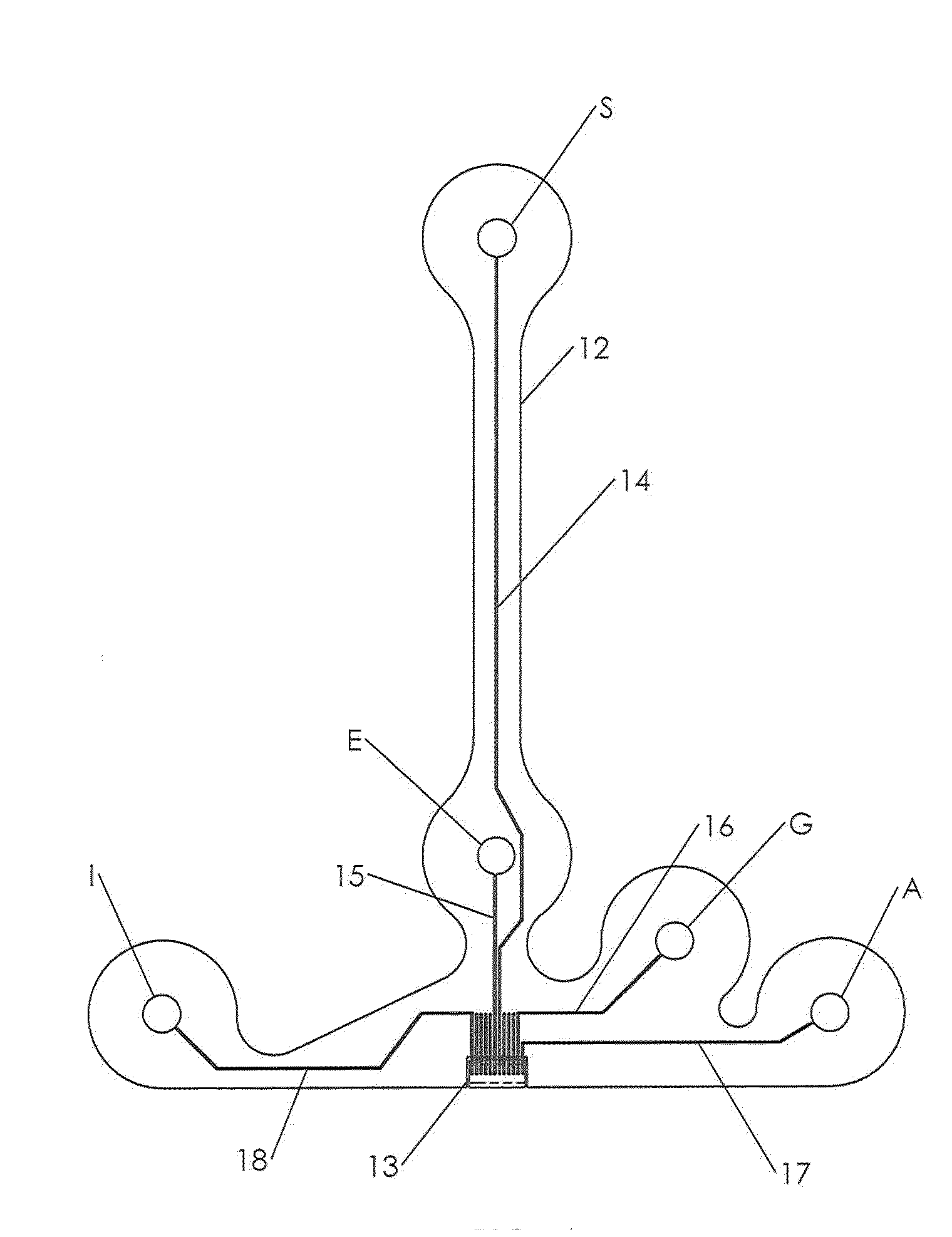
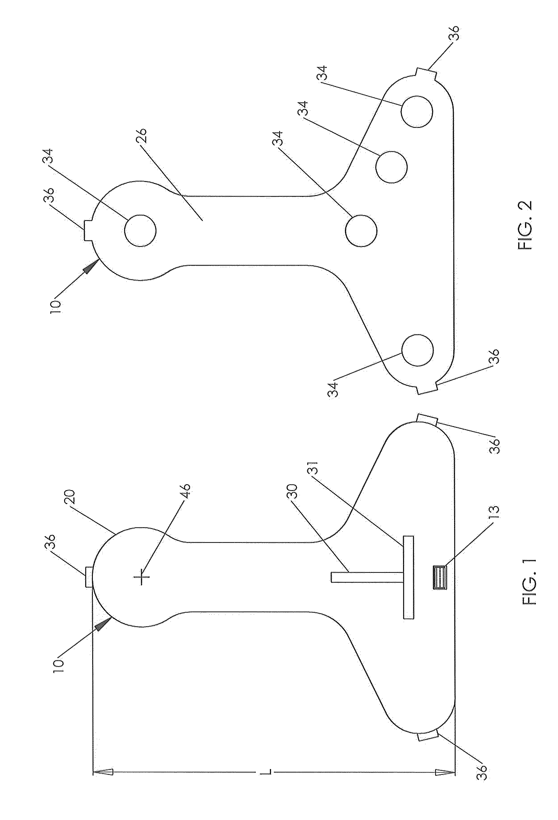
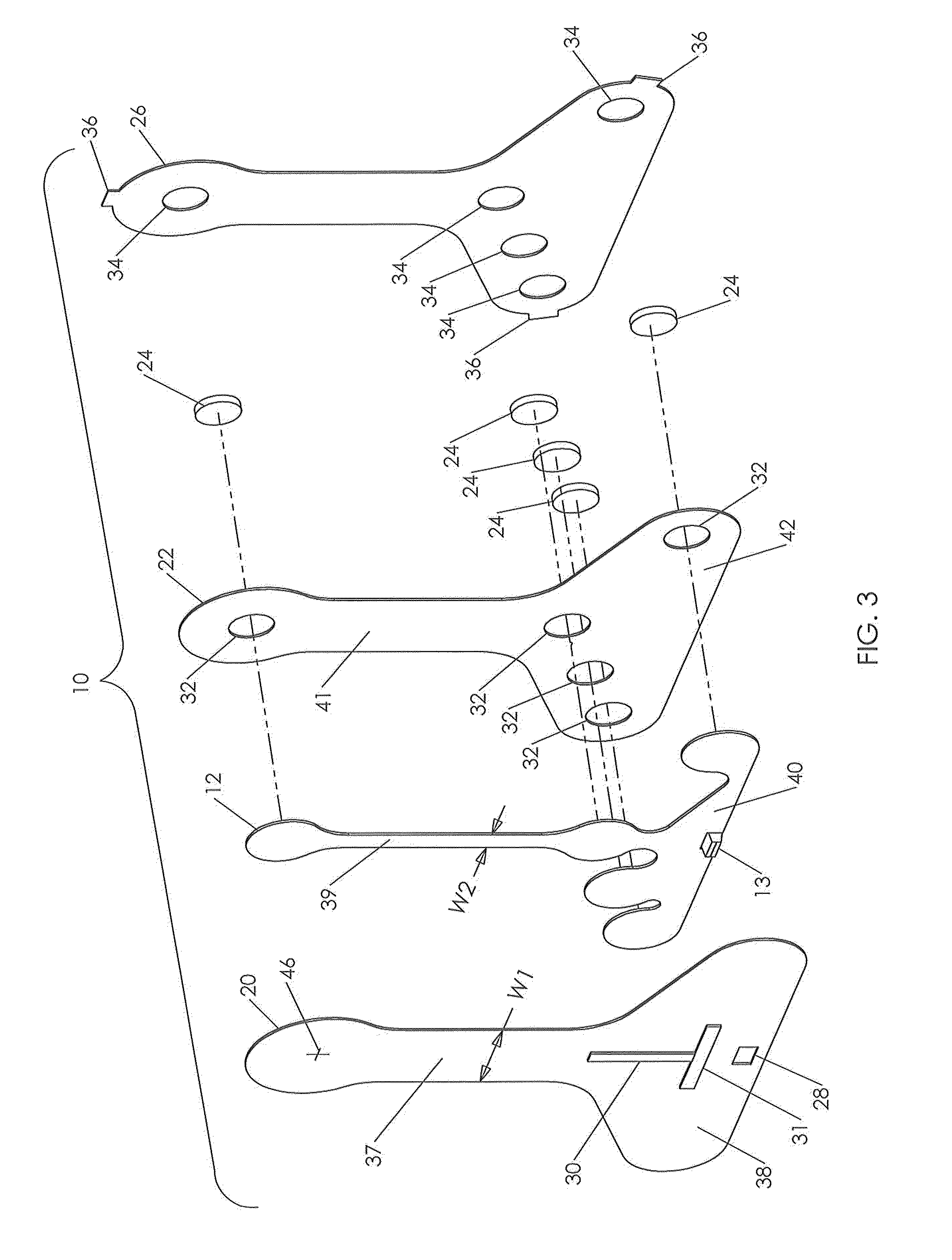
[0068]Referring first to FIGS. 1-4 there is shown a physiological sensor device or patch 10 according to one embodiment of the present invention. FIG. 1 is a front view of the physiological sensor device or patch device 10. As used herein and in the claims the term “front” is understood to re...


PUM


Abstract

A physiological sensor device is attachable to the skin of a person for collecting physiological signals generated by the person's body. The device includes a flexible front layer made of a material that does not conduct electricity and a flexible back layer made of a material that does not conduct electricity. A flexible intermediate layer made of a material that does not conduct electricity is sandwiched between and fixed to the front layer and the back layer. Electrodes and electrical conductors are fixed to a back side of the intermediate layer. Each of the electrodes is attached to one of the electrical conductors and all of the electrical conductors are attached to a single common connector that protrudes through a portal in the front layer. A conductive gel pad is adhered to and aligned with each of the electrodes and protrudes through a portals in the back layer to contact the skin of a person when the physiological sensor device is attached to the skin of a person. Each layer of the physiological sensor device has, when attached to a standing person's chest, a vertically extending portion with a horizontally extending portion located at a lower end of the vertically extending portion to give the physiological sensor device a shape like an inverted T. The vertically extending portion is intended to overly a person's sternum and is sized to comfortably fit either a male or female patient.

Description

CROSS REFERENCE TO RELATED APPLICATION[0001]This is a continuation-in-part of application Ser. No. 10 / 476,437 filed on Oct. 30, 2003.FIELD OF THE INVENTION[0002]The present invention relates to a single use disposable physiological sensor device or patch attachable to the skin of a human subject for collecting certain physiological signals generated by the subject's body over an extended period of time. Physiological data collected by the device may be used in generating an electrocardiogram and / or temperature and / or respiration data from the human subject in a continuous manner over an extended period of time of twenty four to forty eight hours.BACKGROUND OF THE INVENTION[0003]The ability to obtain electrical activity of the human heart from the surface of the skin that was effectuated by Augustus De'sire Waller in 1887 required the subject's limbs to be submersed in saline. In 1912 Willem Einthoven defined lead positions I, II and III which became known as Einthoven's Triangle. Th...

Claims


Application Information

Patent Timeline
Patent Type & Authority Applications(United States)
IPC IPC(8): A61B5/0408
CPCA61B5/0006A61B5/04085A61B5/04325A61B2560/0468A61B5/6833A61B2560/0271A61B2560/0412A61B5/1112A61B5/282A61B5/335
Inventor PARKER, III, JOHN W.MCGUSTY, EDWIN A.VOSCH, MICHAEL J.
Owner HALTHION MEDICAL TECH INC
Why Eureka
Try Eureka