

Fuel supply control apparatus for internal combustion engine and fuel supply control method thereof
a fuel supply control and internal combustion engine technology, applied in the direction of electrical control, process and machine control, instruments, etc., can solve the problems of high cost performance and difficult control of excessive fuel amount with high precision, and achieve the effects of reducing excessive fuel flow amount, high precision and low cos
- Summary
- Abstract
- Description
- Claims
- Application Information
AI Technical Summary
Benefits of technology
Problems solved by technology
Method used
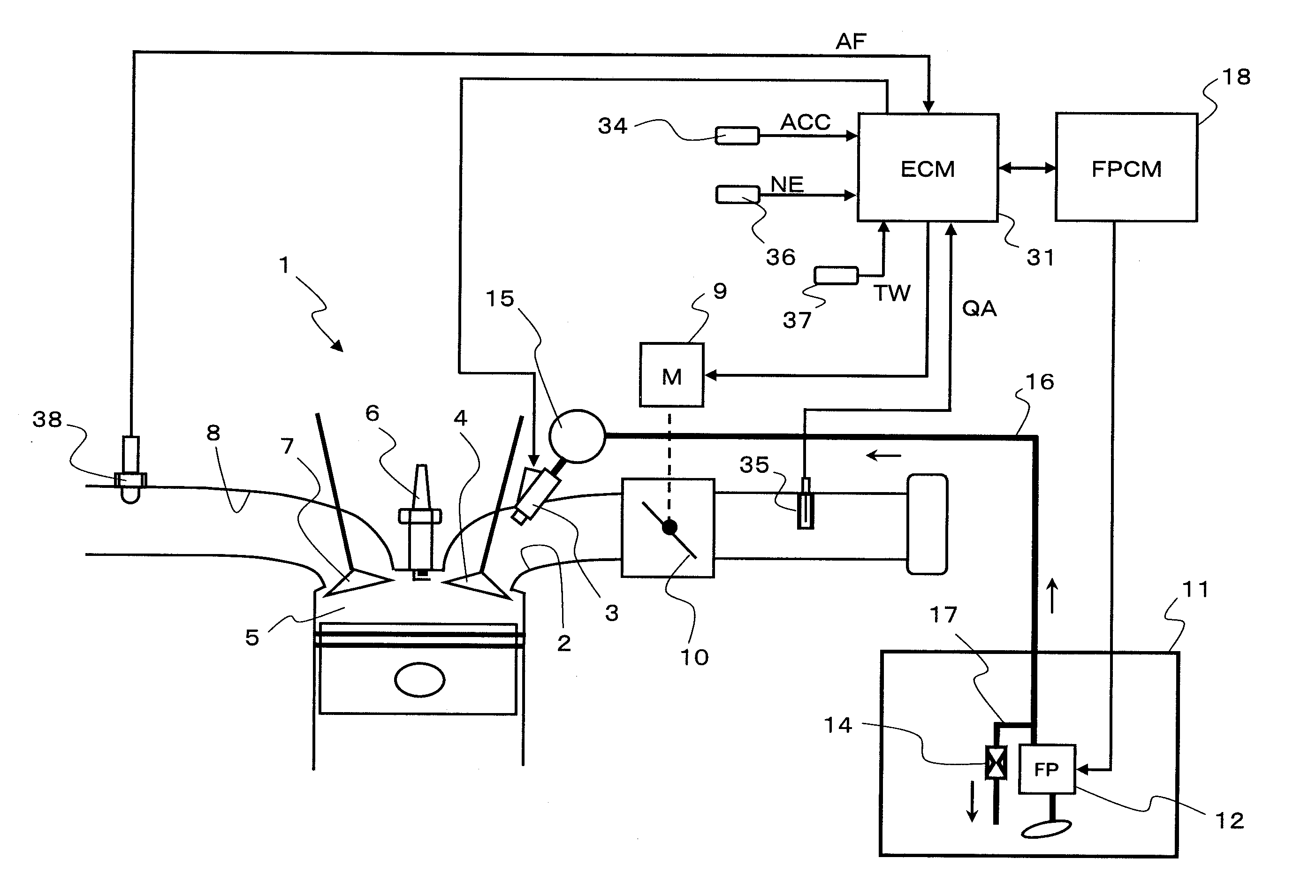
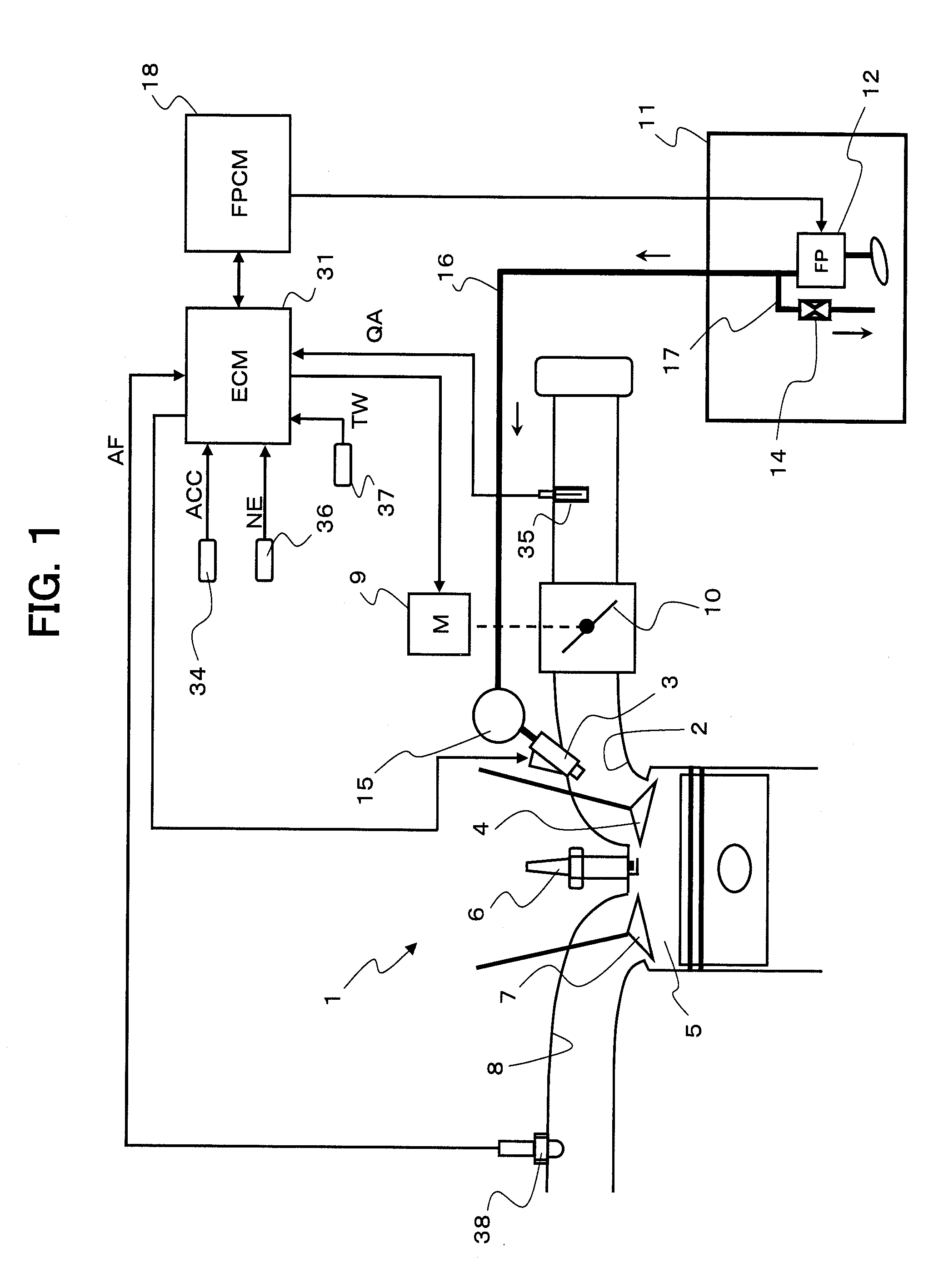
Image

Examples
second embodiment
[0093]Still further, in a system in which the drive current for fuel pump 12 is controlled, it is possible to perform learning in that a target drive current is increased or reduced based on the air-fuel ratio change for when the drive current is temporarily reduced, and thus, the discharge pressure of fuel pump 12 is varied. A second embodiment in such a configuration will be described hereunder in accordance with flowcharts of FIG. 4 and FIG. 5.
[0094]FIG. 4 is the flowchart illustrating a computing process of a target pump drive current, which is interruptedly executed for each set time by ECM 31.
[0095]In step S401, a basic drive current ABASE is calculated according to the operating conditions of internal combustion engine 1.
[0096]The basic drive current ABASE is set as a value at which the excessive fuel is relieved by pressure regulator 14 even if there are the characteristic variations in fuel pump 12. Furthermore, since the variations in fuel pressure are increased on the hig...
first embodiment
[0130]Therefore, in the first embodiment described above, the change of the fuel pressure PF for when the drive voltage is temporarily reduced is detected as the change of the air-fuel ratio which is detected by air-fuel ratio sensor 38. However, the configuration may be such that the change of the fuel pressure is estimated based on the drive current, and if such a configuration is applied, the estimation of the change of the fuel pressure can be performed by using air-fuel ratio sensor 38, and also, by monitoring the drive current.
[0131]In the configuration in which the change of the fuel pressure is estimated based on the change of the pump drive current, the change of the fuel pressure can be estimated at responsibility higher than that for the case in which the change of the air-fuel ratio is detected, and it is possible to promptly correct the pump drive current to a level at which the excessive fuel amount becomes minimum without adversely effecting the operability of the eng...
PUM
 Abstract
Description
Claims
Application Information