
Multi-Resolution Switched Audio Encoding/Decoding Scheme

a switched audio and encoding technology, applied in the field of low bit rate audio coding schemes, can solve the problems of poor quality of speech poor quality of other signals at low bitrates, and achieve the effect of at least reducing or even completely avoiding artifacts

Active Publication Date: 2011-09-29
FRAUNHOFER GESELLSCHAFT ZUR FOERDERUNG DER ANGEWANDTEN FORSCHUNG EV +1
View PDF6 Cites 147 Cited by
  • Summary
  • Abstract
  • Description
  • Claims
  • Application Information

AI Technical Summary

Benefits of technology

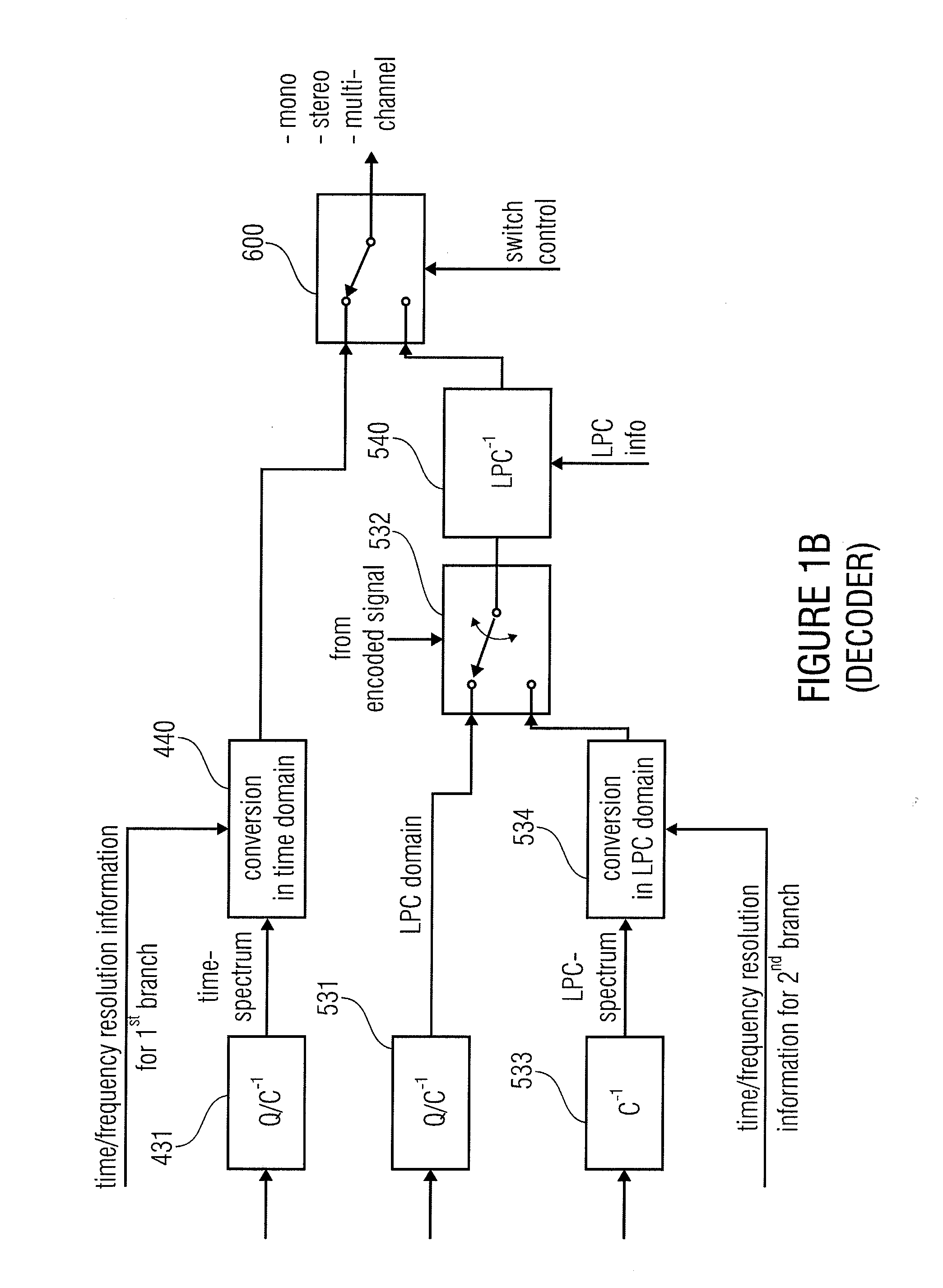
The present invention is about an audio encoder and decoder that use a hybrid or dual-mode switched coding / encoding scheme. This means that the best coding algorithm can be selected for a certain signal characteristic, rather than trying to find a perfect match for all signal characteristics. The encoder uses a first coding branch to convert the audio signal to a spectral domain, and a second coding branch to convert the signal from the input domain to the output domain. The decoder switches between the two branches to ensure that the optimally matching coding algorithm is selected for each audio signal portion. This results in better audio quality and more efficient use of computational resources.

Problems solved by technology

Problematic, however, is the quality of speech signals at low bitrates.
Speech coding schemes show a high quality for speech signals even at low bitrates, but show a poor quality for other signals at low bitrates.

Method used


Image

  • Multi-Resolution Switched Audio Encoding/Decoding Scheme
  • Multi-Resolution Switched Audio Encoding/Decoding Scheme
  • Multi-Resolution Switched Audio Encoding/Decoding Scheme

Examples


Embodiment Construction

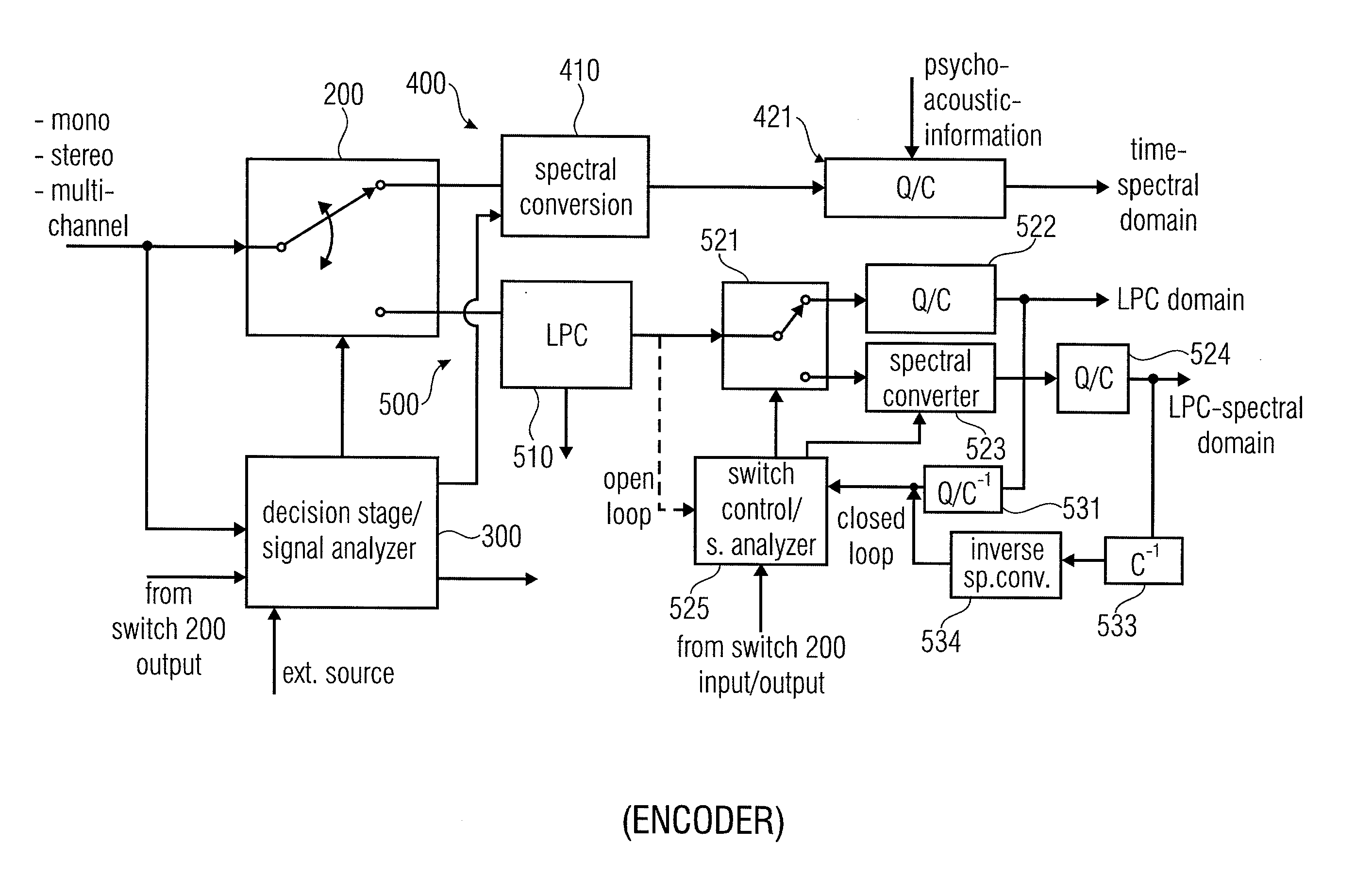
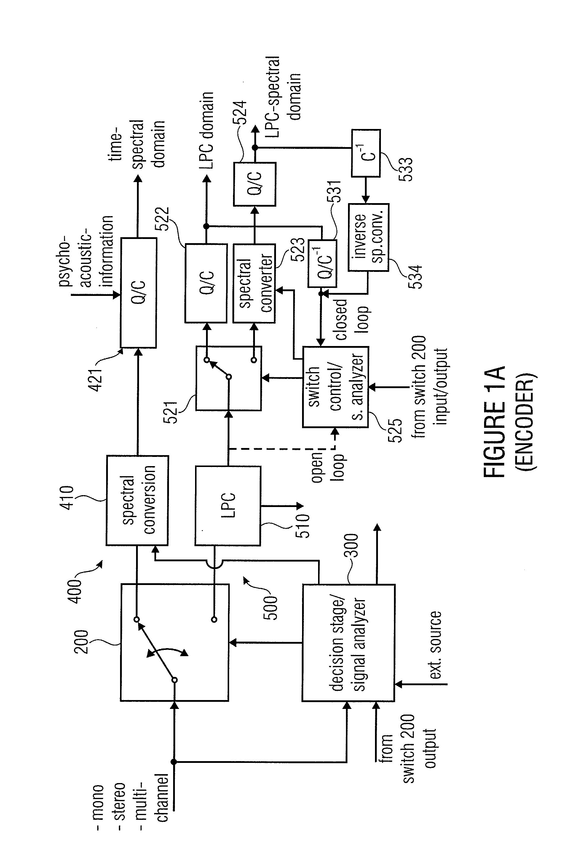
[0064]FIG. 11A illustrates an embodiment of an audio encoder for encoding an audio signal. The encoder comprise a first coding branch 400 for encoding an audio signal using a first coding algorithm to obtain a first encoded signal.

[0065]The audio encoder furthermore comprises a second coding branch 500 for encoding an audio signal using a second coding algorithm to obtain a second encoded signal. The first coding algorithm is different from the second coding algorithm. Additionally, a first switch 200 for switching between the first coding branch and the second coding branch is provided so that, for a portion of the audio signal, either the first encoded signal or the second encoded signal is in an encoder output signal 801.

[0066]The audio encoder illustrated in FIG. 11A additionally comprises a signal analyzer 300 / 525, which is configured for analyzing a portion of the audio signal to determine, whether the portion of the audio signal is represented as the first encoded signal or t...


PUM


Abstract

An audio encoder for encoding an audio signal has a first coding branch, the first coding branch comprising a first converter for converting a signal from a time domain into a frequency domain. Furthermore, the audio encoder has a second coding branch comprising a second time / frequency converter. Additionally, a signal analyzer for analyzing the audio signal is provided. The signal analyzer, on the hand, determines whether an audio portion is effective in the encoder output signal as a first encoded signal from the first encoding branch or as a second encoded signal from a second encoding branch. On the other hand, the signal analyzer determines a time / frequency resolution to be applied by the converters when generating the encoded signals. An output interface includes, in addition to the first encoded signal and the second encoded signal, a resolution information identifying the resolution used by the first time / frequency converter and used by the second time / frequency converter.

Description

CROSS-REFERENCE TO RELATED APPLICATIONS[0001]This application is a continuation of copending International Application No. PCT / EP2009 / 007205, filed Oct. 7, 2009, which is incorporated herein by reference in its entirety, and additionally claims priority from European Applications Nos. 09002271.6, filed Feb. 18, 2009, and EP 08017663.9, filed Oct. 8, 2008 and U.S. Patent Application No. 61 / 103,825, filed Oct. 8, 2008, which are all incorporated herein by reference in their entirety.BACKGROUND OF THE INVENTION[0002]The present invention is related to audio coding and, particularly, to low bit rate audio coding schemes.[0003]In the art, frequency domain coding schemes such as MP3 or AAC are known. These frequency-domain encoders are based on a time-domain / frequency-domain conversion, a subsequent quantization stage, in which the quantization error is controlled using information from a perceptual module, and an encoding stage, in which the quantized spectral coefficients and correspond...

Claims


Application Information

Patent Timeline
Patent Type & Authority Applications(United States)
IPC IPC(8): G06F17/00G10L19/00G10L19/008G10L19/02G10L19/16G10L19/18
CPCG10L19/18G10L19/173G10L19/008G10L19/0017G10L19/0212G10L2019/0008G10L19/02G10L19/04H03M7/30
Inventor NEUENDORF, MAXBAYER, STEFANLECOMTE, JEREMIEFUCHS, GUILLAUMEROBILLIARD, JULIENRETTELBACH, NIKOLAUSNAGEL, FREDERIKGEIGER, RALFMULTRUS, MARKUSGRILL, BERNHARDGOURNAY, PHILIPPESALAMI, REDWAN
Owner FRAUNHOFER GESELLSCHAFT ZUR FOERDERUNG DER ANGEWANDTEN FORSCHUNG EV
Learn More