Disk drive device improved in Anti-vibration characteristic

a technology of drive device and anti-vibration, which is applied in the direction of sliding contact bearings, instruments, record information storage, etc., can solve the problems of excessive increase of contact between the surface, and substantial reduction of the stiffness so as to reduce the stiffness in the thrust direction of the bearing unit, the thrust dynamic pressure becomes large, and the dynamic pressure in the pump-in direction is excessively increased

Inactive Publication Date: 2011-02-10
SAMSUNG ELECTRO MECHANICS JAPAN ADVANCED TECHNOLOGY CO LTD
View PDF8 Cites 10 Cited by
  • Summary
  • Abstract
  • Description
  • Claims
  • Application Information

AI Technical Summary

Benefits of technology

[0007]The present invention has been made in view of these situations, and a purpose of the invention is to provide a disk drive device in which, when a drive current is reduced, the stiffness of a fluid dynamic bearing unit is maintained and therefore read / write of data can be stably performed even under an environment with a lot of vibrations.
[0009]The rotating body generates thrust dynamic pressure in the lubricant and floats therein by rotating at a predetermined rotating speed or more. At the time, if the stiffness in the thrust direction of a bearing unit is decreased due to a reduction in a drive current, the space where the lubricant is present, in the first thrust dynamic pressure generating portion or in the second thrust dynamic pressure generating portion, becomes narrow because the rotating body is biased in the rotational axis direction. As a result, the thrust dynamic pressure becomes large due to the bias of the rotating body, resulting in a phenomenon in which the floating force of the rotating body is increased and the bias is accelerated. In other words, the dynamic pressure in the pump-in direction is excessively increased and maintenance of a balanced floating posture is hampered, thereby causing a state in which the stiffness of the bearing unit is substantially decreased. In addition, the gap between the rotating body and a fixed body facing the rotating body, in the first thrust dynamic pressure generating portion or in the second thrust dynamic pressure generating portion, becomes scarce due to an excessive bias of the rotating body, thereby sometimes causing a contact between the surface of the fixed body and that of the rotating body. In this case, not only an increase in a drive current due to an increase in load or a decrease in the lifetime due to wear are caused, but also deterioration in the rotational accuracy, etc., is caused due to the contact, thereby possibly causing an increase in errors in reading / writing data. Accordingly, with a bearing unit having a dynamic pressure generation characteristic in which, when a rotating body is biased in the rotational axis direction from the state where the rotating body is floating in lubricant, the sum of the changes in the dynamic pressure in the pump-out direction is larger than that of the changes in the dynamic pressure in the pump-in direction, an increase in the dynamic pressure in the pump-in direction as the whole bearing unit is suppressed. As a result, an excessive increase in the floating force, occurring while the rotating body is floating, can be suppressed. That is, a bias of the rotating body can be suppressed, and accordingly, a bearing unit with high stiffness by which the rotating body is hardly biased can be formed. Therefore, the relative distance between a recording disk and a magnetic head is stabilized and read / write of data can be stably performed even under an environment with a lot of vibrations.

Problems solved by technology

In other words, the dynamic pressure in the pump-in direction is excessively increased and maintenance of a balanced floating posture is hampered, thereby causing a state in which the stiffness of the bearing unit is substantially decreased.
In addition, the gap between the rotating body and a fixed body facing the rotating body, in the first thrust dynamic pressure generating portion or in the second thrust dynamic pressure generating portion, becomes scarce due to an excessive bias of the rotating body, thereby sometimes causing a contact between the surface of the fixed body and that of the rotating body.
In this case, not only an increase in a drive current due to an increase in load or a decrease in the lifetime due to wear are caused, but also deterioration in the rotational accuracy, etc., is caused due to the contact, thereby possibly causing an increase in errors in reading / writing data.

Method used


Image

  • Disk drive device improved in Anti-vibration characteristic
  • Disk drive device improved in Anti-vibration characteristic
  • Disk drive device improved in Anti-vibration characteristic

Examples


Embodiment Construction

[0024]The invention will now be described by reference to the preferred embodiments. This does not intend to limit the scope of the present invention, but to exemplify the invention.

[0025]Hereinafter, embodiments of the present invention will be described based on the accompanying drawings. The present embodiments are adopted in brushless motors that are to be mounted on hard disk drive devices (sometimes referred to as HDDs or disk drive devices) to drive recording disks, or in disk drive motors that are to be mounted in optical disk recording and reproducing devices (also simply referred to as disk drive devices), such as CD (Compact Disc) devices and DVD (Digital Versatile Disc) devices.

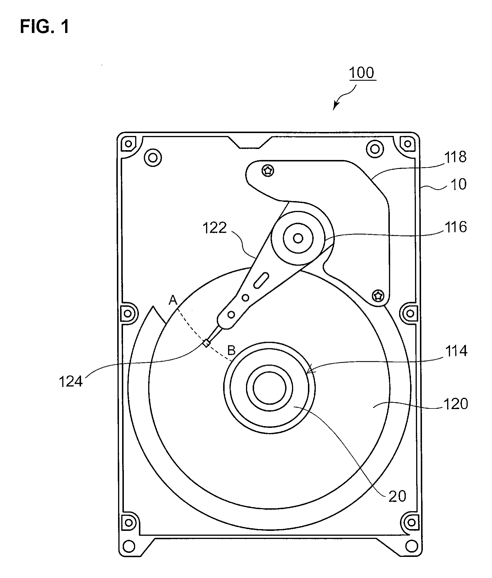
[0026]FIG. 1 is an illustrative view illustrating the internal structure of an HDD 100 (hereinafter referred to as a disk drive device 100), an example of a disk drive device according to the present embodiment. FIG. 1 illustrates the state where a cover is removed in order to expose the internal ...


PUM

PropertyMeasurementUnit
distanceaaaaaaaaaa
forceaaaaaaaaaa
forceaaaaaaaaaa

Abstract

A disk drive device includes a rotating body, a fluid dynamic bearing unit that rotatably supports the rotating body, and a drive unit. The fluid dynamic bearing unit has: a lubricant holding portion in which lubricant is held; a first thrust dynamic pressure groove with which a first thrust dynamic pressure generating portion for generating the dynamic pressure in the pump-in direction, which is oriented toward the inside of the lubricant holding portion, is structured; and a second thrust dynamic pressure groove with which a second thrust dynamic pressure generating portion for generating at least the dynamic pressure in the pump-out direction, is structured. The first thrust dynamic pressure generating portion and the second thrust dynamic pressure generating portion have dynamic pressure generation characteristics in which, when the rotating body is biased in the rotational axis direction from the state where the rotating body is floating in the lubricant, the sum of the changes in the dynamic pressure in the pump-out direction is larger than that of the changes in the dynamic pressure in the pump-in direction.

Description

CROSS-REFERENCE TO RELATED APPLICATION[0001]This application is based upon and claims the benefit of priority from the prior Japanese Patent Application No. 2009-181545, filed on Aug. 4, 2009, the entire content of which is incorporated herein by reference.BACKGROUND OF THE INVENTION[0002]1. Field of the Invention[0003]The present invention relates to a disk drive device, in particular, to a disk drive device in which its anti-vibration characteristic is improved while reducing a drive current.[0004]2. Description of the Related Art[0005]In recent years, disk drive devices, such as Hard Disk Drives (HDDs), have been developed to be small in size and large in capacity, and been widely used in many electrical appliances. Therefore, disk drive devices have been used in a wide variety of environments. In particular, disk drive devices are being mounted in portable devices called mobile devices. Mobile devices are frequently used in environments with a lot of vibrations, and therefore th...

Claims


Application Information

Patent Timeline
Patent Type & Authority Applications(United States)
IPC IPC(8): F16C32/06G11B25/00
CPCF16C17/04F16C17/045F16C2370/12F16C33/107G11B19/2036F16C17/107
Inventor YAMADA, TAKUJIKODAMA, MITSUO
Owner SAMSUNG ELECTRO MECHANICS JAPAN ADVANCED TECHNOLOGY CO LTD
Why Eureka
Try Eureka