Differential resonant sensor apparatus and method for detecting relative humidity

Active Publication Date: 2011-10-06
HONEYWELL ROMANIA
View PDF7 Cites 13 Cited by
  • Summary
  • Abstract
  • Description
  • Claims
  • Application Information

AI Technical Summary

Benefits of technology

[0010]It is a further aspect of the disclosed embodiments to provide for an improved method for fabricating a differ

Problems solved by technology

Problems associated with such capacitive sensors includes cost, a lack of long term performance stability and poor drift behavior due to poor baseline stability (i.e., recovery of the sensor signal to the same response level in the absence of t

Method used


Image

  • Differential resonant sensor apparatus and method for detecting relative humidity
  • Differential resonant sensor apparatus and method for detecting relative humidity
  • Differential resonant sensor apparatus and method for detecting relative humidity

Examples


Embodiment Construction

[0024]The particular values and configurations discussed in these non-limiting examples can be varied and are cited merely to illustrate at least one embodiment and are not intended to limit the scope thereof.

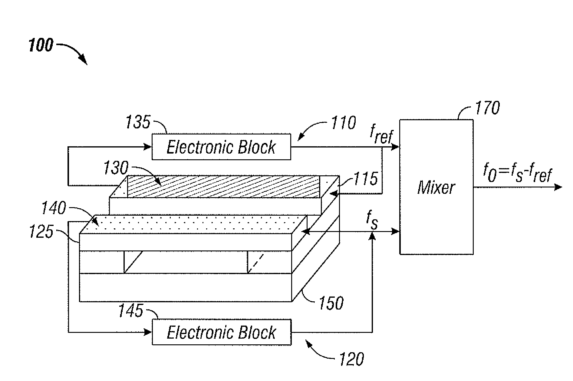
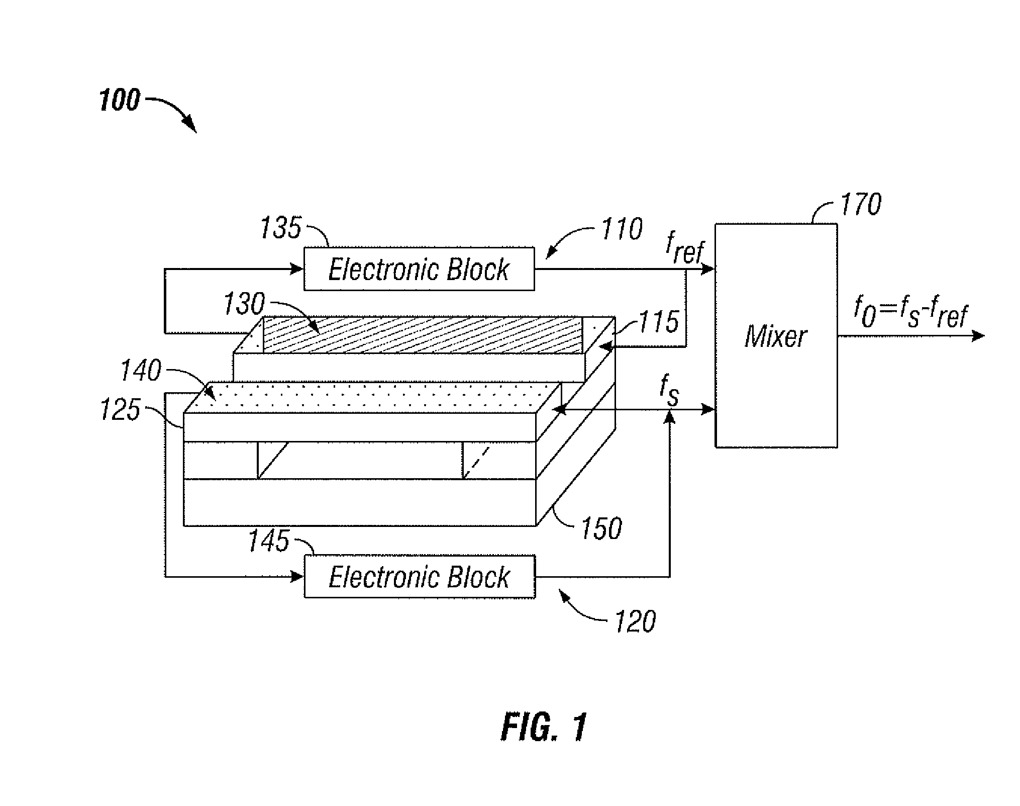
[0025]FIG. 1 illustrates a perspective view of a differential resonant sensor apparatus 100, in accordance with the disclosed embodiments. The differential resonant sensor apparatus 100 can be employed to detect relative humidity (RH) in an ambient air utilizing MEMS-NEMS silicon technology. The differential resonant sensor apparatus 100 can be integrated on a chip 150 of a substrate wafer (e.g., silicon wafer, not shown) together with the differential interrogation electronic blocks 135 and 145. The sensor apparatus 100 includes a sensing loop 120, a reference loop 110 and a mixer 170 located at the output of the electronic blocks 135 and 145 for resonance frequency measurement. The sensing loop 120 further includes a sensing resonant beam 125 and the reference loop 110 includ...


PUM


Abstract

A differential resonant sensor apparatus and method for detecting relative humidity in an ambient air. The apparatus generally includes a sensing loop, a reference loop and a mixer. A hydrophilic sensing layer can be deposited on a sensing resonant beam and a corresponding hydrophobic reference layer can be deposited on a reference resonant beam for detecting water vapor concentration in the ambient air. The hydrophobic reference layer possesses similar visco-elastic properties as the hydrophilic sensing layer with no water absorption properties. A differential reading electronic circuit may be interconnected with each resonant beam for signal processing. The absorbed humidity with respect to the sensing resonant beam changes the mechanical resonance frequency, which can be detected as a change in the electric resonance frequency of the associated electronic circuit.

Description

CROSS-REFERENCE TO PROVISIONAL APPLICATION[0001]This non-provisional patent application claims the benefit under 35 U.S.C. §119(e) to U.S. Provisional Patent Application Ser. No. 61 / 318,857 filed on Mar. 30, 2010, entitled “Differential Resonant Sensor Apparatus and Method for Detecting Relative Humidity,” which is hereby incorporated by reference in its entirety.TECHNICAL FIELD[0002]Embodiments are generally related to sensing devices and techniques. Embodiments are also related to differential resonant sensors. Embodiments are additionally related to methods for detecting relative humidity in ambient air.BACKGROUND OF THE INVENTION[0003]Numerous applications require controlling a defined environment's air quality characteristics, including providing an environment having a narrow range of relative humidity (RH) and / or preventing the creation of extreme relative humidity conditions. Indoor air quality can be impacted by air contaminants such as humidity, volatile organic compounds ...

Claims


Application Information

Patent Timeline
IPC IPC(8): G01N27/12
CPCG01N29/022G01N29/036G01N29/30G01N29/32G01N2291/0427G01N2291/014G01N2291/0215G01N2291/0256G01N2291/02845G01N29/326
Inventor COBIANU, CORNELSERBAN, BOGDANMIHAILA, MIHAI N.
Owner HONEYWELL ROMANIA
Why Eureka
Try Eureka