Arrangement and method for influencing and/or detecting magnetic particles

a magnetic particle and arrangement technology, applied in the field of arrangement for influencing and/or detecting magnetic particles, can solve the problems of induced voltage in the receiving means, low signal noise, and already relatively high switching loss at that frequency, so as to reduce the number of switching events, avoid additional noise in the signal, and facilitate filtering

Inactive Publication Date: 2011-10-06
KONINKLIJKE PHILIPS ELECTRONICS NV
View PDF3 Cites 7 Cited by
  • Summary
  • Abstract
  • Description
  • Claims
  • Application Information

AI Technical Summary

Benefits of technology

[0018]The switching frequency is preferably in the order of the bandwidth of the drive field system, which is only 1% of the operation frequency which has the advantage that the number of switching events is greatly reduced. A preferred frequency range is from 0 to 5 kHz, in particular from 0 to 2 kHz.
[0019]In addition or instead of switching the coupling, the resonance frequency of the energy storage tank circuits can be varied by switched reactive elements. As the frequency of switching is preferably in the order of the drive field bandwidth, it can be synchronised to the MPI sequence to avoid additional noise in the signal and ease the filtering. Thus, the switching can be performed at times where the field free point is moving slowly and no or little signal is generated anyway.

Problems solved by technology

The switching losses at that frequency are already relatively high.
One of the signal detection problems occurring in such an arrangement is the induced voltage in the receiving means due to the existence of the magnetic drive field.

Method used


Image

  • Arrangement and method for influencing and/or detecting magnetic particles
  • Arrangement and method for influencing and/or detecting magnetic particles
  • Arrangement and method for influencing and/or detecting magnetic particles

Examples


Embodiment Construction

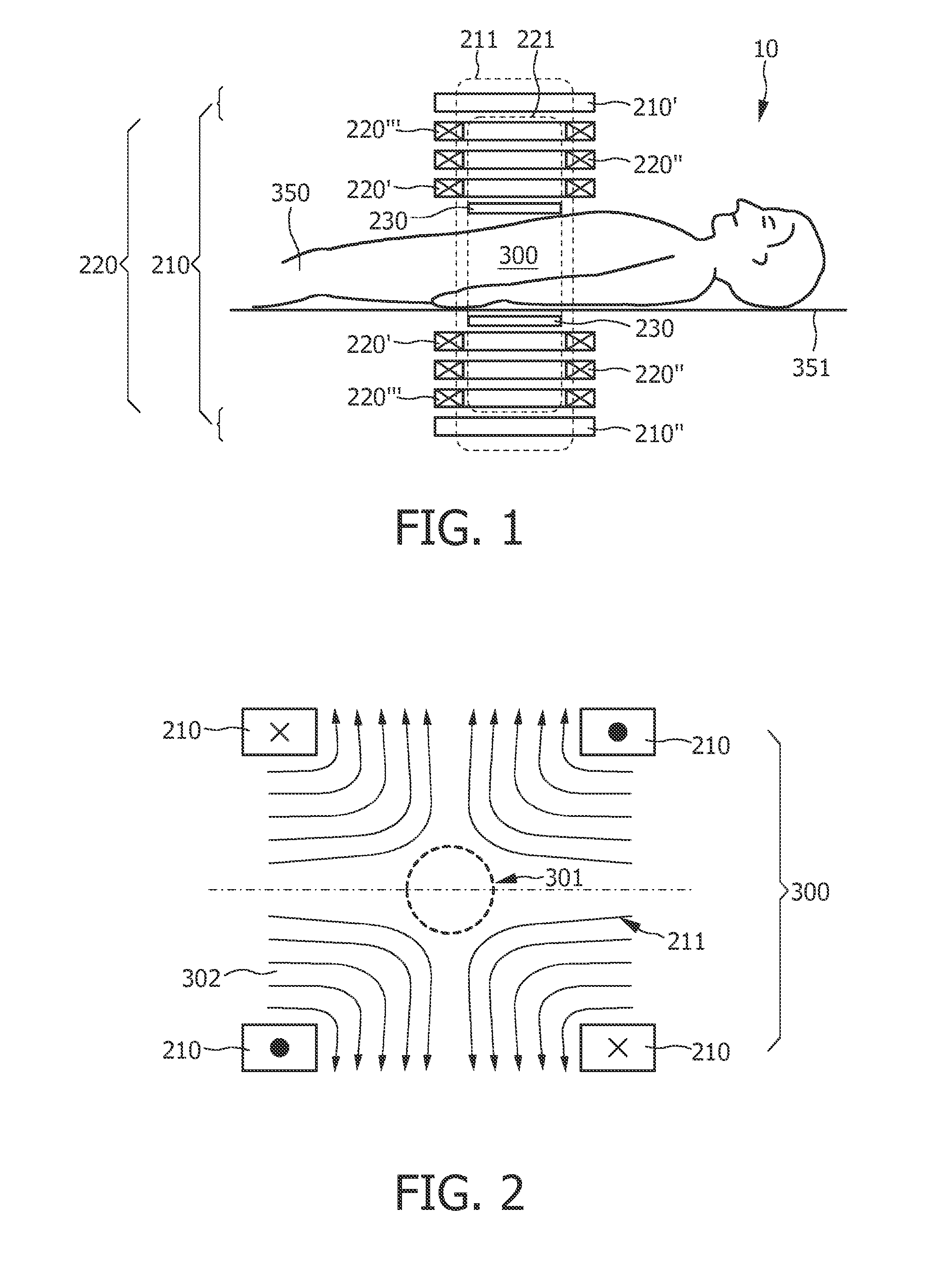
[0034]FIG. 1 shows an arbitrary object to be examined by means of a MPI arrangement 10. The reference numeral 350 in FIG. 1 denotes an object, in this case a human or animal patient, who is arranged on a patient table 351, only part of the top of which is shown. Prior to the application of the method according to the present invention, magnetic particles 100 (not shown in FIG. 1) are arranged in a region of action 300 of the inventive arrangement 10. Especially prior to a therapeutical and / or diagnostical treatment of, for example, a tumor, the magnetic particles 100 are positioned in the region of action 300, e.g. by means of a liquid (not shown) comprising the magnetic particles 100 which is injected into the body of the patient 350.

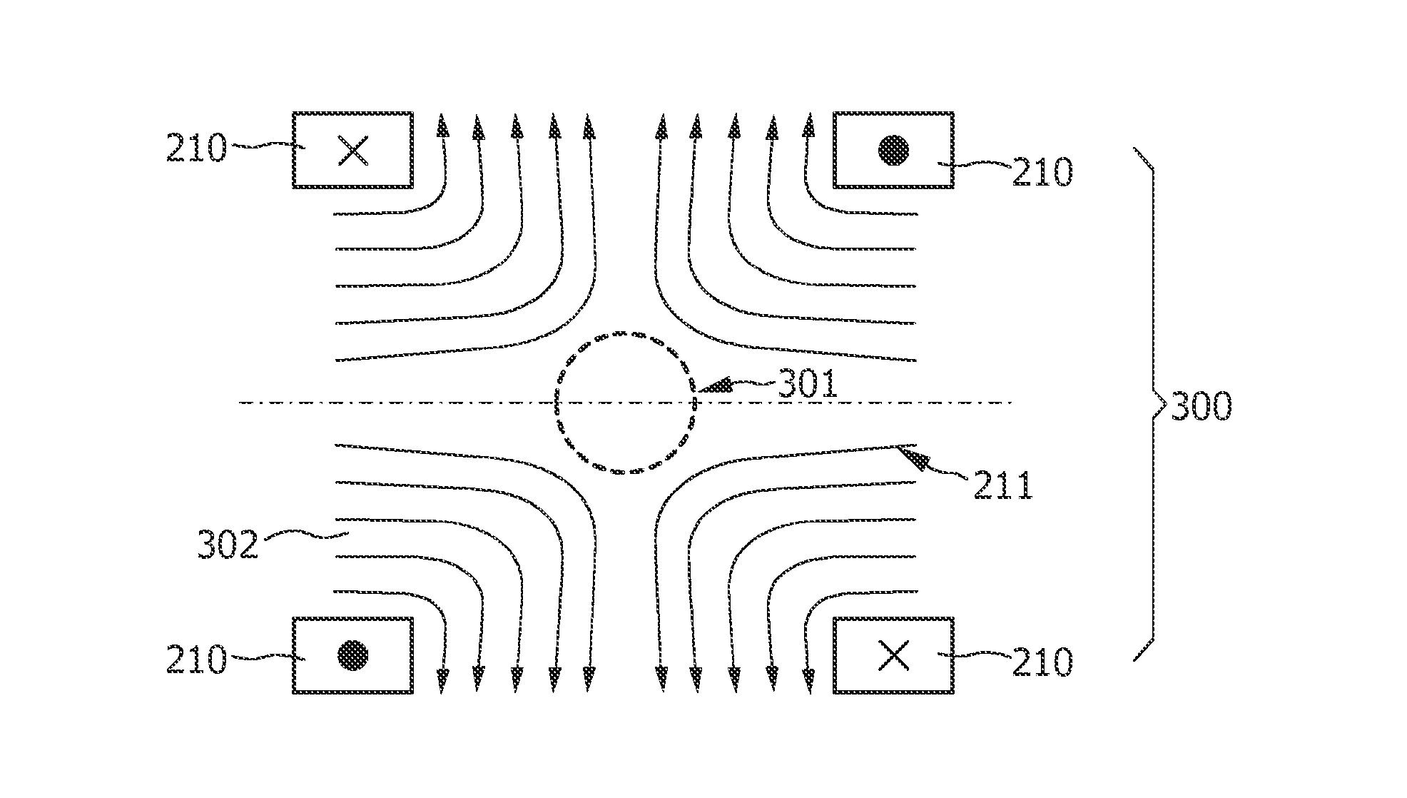
[0035]As an example of an embodiment of the present invention, an arrangement 10 is shown in FIG. 2 comprising a plurality of coils forming a selection means 210 whose range defines the region of action 300 which is also called the region of treatment ...


PUM


Abstract

The present invention relates to an arrangement (10) and a corresponding method for influencing and/or detecting magnetic particles in a region of action (300). To store the required reactive energy a tank circuit (453) is provided, which is preferably operating at the centre frequency of the MPI drive field. Reactive elements (C4, L2), in particular capacitors and/or inductors, couple one or more tank circuit (453) to the drive field resonator (454, 220). The coupling strength is preferably varied by switching additional reactive elements (C5) into and out of the coupling unit (452) to vary the strength of coupling.

Description

FIELD OF THE INVENTION[0001]The present invention relates to an arrangement for influencing and / or detecting magnetic particles in a region of action. The present invention relates further to a corresponding method, to a drive field generator unit for such an arrangement and to a computer program.BACKGROUND OF THE INVENTION[0002]An arrangement of this kind is known from German patent application DE 101 51 778 A1. In the arrangement described in that publication, first of all a magnetic selection field having a spatial distribution of the magnetic field strength is generated such that a first sub-zone having a relatively low magnetic field strength and a second sub-zone having a relatively high magnetic field strength are formed in the examination zone. The position in space of the sub-zones in the examination zone is then shifted, so that the magnetization of the particles in the examination zone changes locally. Signals are recorded which are dependent on the magnetization in the e...

Claims


Application Information

Patent Timeline
Patent Type & Authority Applications(United States)
IPC IPC(8): G01R33/02
CPCA61B5/05H03F3/005A61B5/0515
Inventor GLEICH, BERNHARD
Owner KONINKLIJKE PHILIPS ELECTRONICS NV
Why Eureka
Try Eureka