Vehicle position recognition system

a technology of vehicle position and recognition system, which is applied in the direction of instruments, surveying and navigation, navigation instruments, etc., can solve the problems of insufficient contribution of technology simply increased or decreased the radius of error range, and insufficient contribution to accurate estimation of vehicle position, etc., to achieve efficient provision of various kinds of guidance

Inactive Publication Date: 2011-10-06
AISIN AW CO LTD
View PDF5 Cites 17 Cited by
  • Summary
  • Abstract
  • Description
  • Claims
  • Application Information

AI Technical Summary

Benefits of technology

[0009]According to the first aspect, the basic error range is adjusted by estimating the error amount(s) caused by the directional error factor(s) that tend(s) to cause the error(s) in the specific direction(s) with respect to the vehicle traveling direction. Thus, it is possible to appropriately adjust the basic error range, taking into account the direction(s) in which the error(s) tend(s

Problems solved by technology

However, in the technology described in the publication No. 2005-249654, the radius of the error range is simply increased or decreased.
Particularly, because the size of the front region of the error range in a vehicle traveling direction in which the vehicle is traveling is equal to the size of the rear region of the error range in the vehicle traveling direct

Method used


Image

  • Vehicle position recognition system
  • Vehicle position recognition system
  • Vehicle position recognition system

Examples


Embodiment Construction

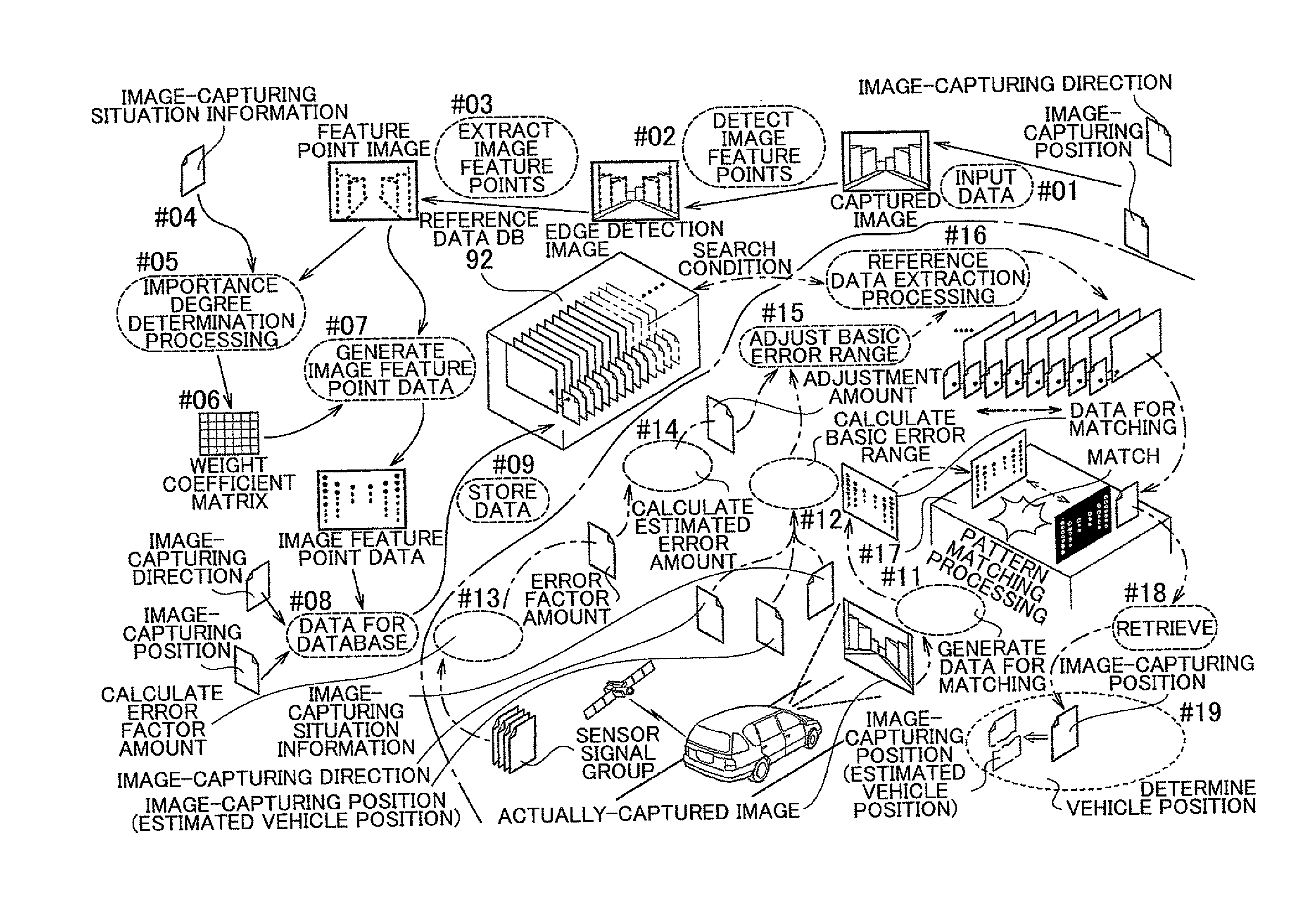
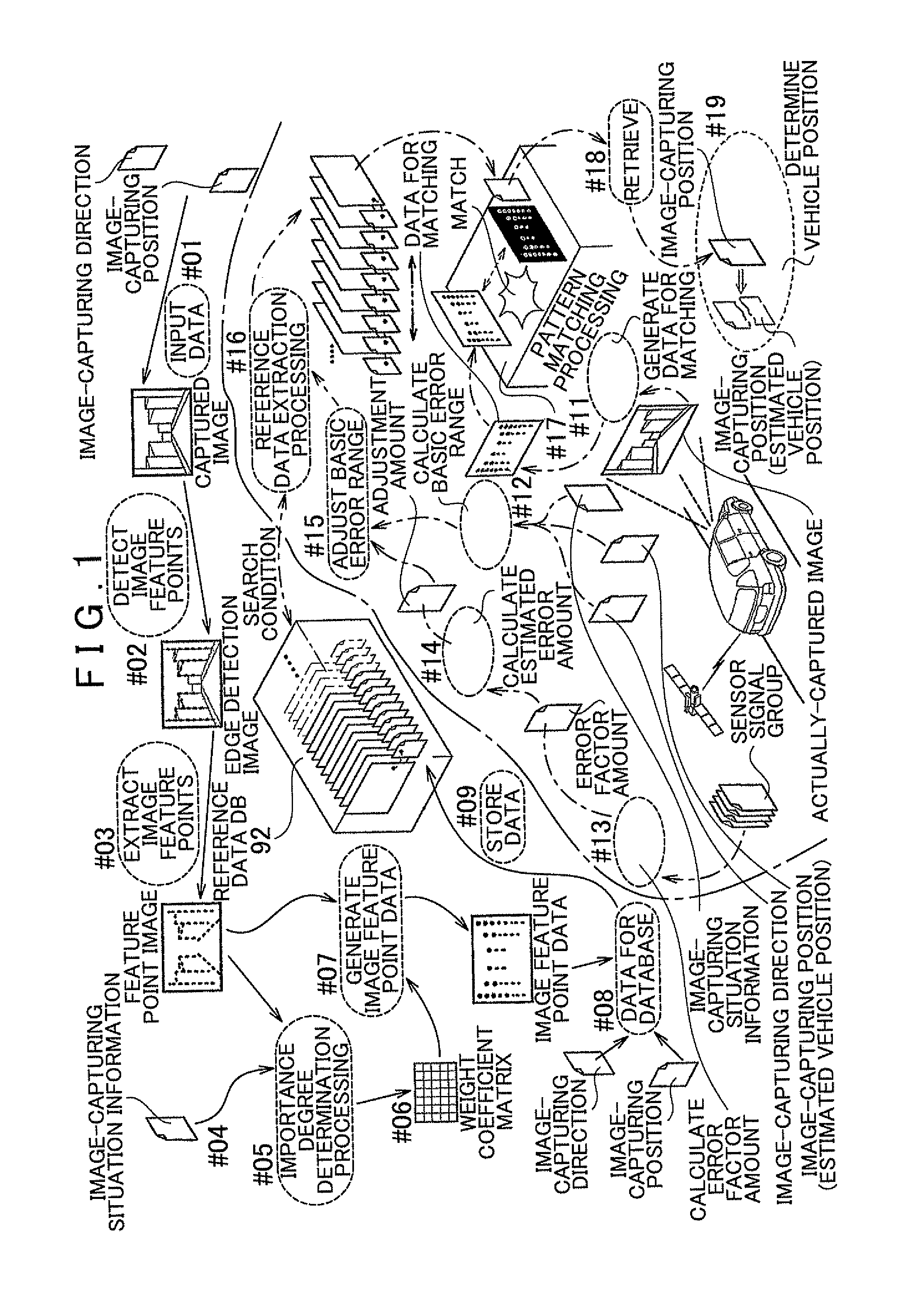
[0019]Hereinafter, an embodiment of the invention will be described in detail with reference to the drawings. FIG. 1 schematically shows the basic concept of a vehicle position recognition system according to the embodiment of the invention, which recognizes, through matching processing, a scenic image captured by a vehicle-mounted camera disposed to capture an image of a scene ahead of a vehicle in a direction in which the vehicle is traveling (hereinafter, referred to as “vehicle traveling direction”), so that a position at which the scenic image is captured, that is, a vehicle position is determined.

[0020]First, a procedure for creating a reference data database (hereinafter, simply referred to as “reference data DB”) 92, which stores a reference data as a matching candidate, will be described. As shown in FIG. 1, first, a captured image obtained by capturing an image of a scene viewed from a vehicle during travel, and image-capturing attribute information are input (step 01). Th...


PUM


Abstract

A vehicle position recognition system calculates an estimated position of a vehicle based on satellite positioning and dead reckoning navigation, and calculates a basic error range in which there is a possibility that the vehicle exists. The system calculates an estimated error amount regarding a directional error factor. The directional error factor is an error factor that tends to cause an error in a specific direction with respect to a vehicle traveling direction. The estimated error amount is an estimated amount of the error that is caused by the directional error factor. The system adjusts the basic error range based on (1) a direction in which the error tends to be caused by the directional error factor and (2) the estimated error amount.

Description

INCORPORATION BY REFERENCE[0001]The disclosure of Japanese Patent Application No. 2010-084678 filed on Mar. 31, 2010 including the specification, drawings and abstract is incorporated herein by reference in its entirety.BACKGROUND OF THE INVENTION[0002]1. Field of the Invention[0003]The invention relates to a vehicle position recognition system that includes a vehicle position calculation unit that calculates an estimated position of a vehicle based on satellite positioning and dead reckoning navigation, and an error range calculation unit that calculates an error range based on the estimated position, taking into account an error in the estimated position.[0004]2. Description of the Related Art[0005]The above-described vehicle position recognition system, which includes the vehicle position calculation unit and the error range calculation unit, is used for calculating a vehicle position in a car navigation apparatus. Japanese Patent Application Publication No. 2005-249654 (JP-A-200...

Claims


Application Information

Patent Timeline
IPC IPC(8): G06K9/46G06F19/00G01C21/00
CPCG01C21/165G01C21/28G01C21/1656
Inventor MIYAJIMA, TAKAYUKI
Owner AISIN AW CO LTD
Why Eureka
Try Eureka