Hob

a technology of helical guide and base body, applied in the field of hob, can solve the problems of comparatively complicated production of basic body with attached helical guide, and achieve the effect of easy production

Active Publication Date: 2011-10-06
KENNAMETAL INC
View PDF11 Cites 18 Cited by
  • Summary
  • Abstract
  • Description
  • Claims
  • Application Information

AI Technical Summary

Benefits of technology

[0009]The object of the invention is to specify a hob which is easy to produce.

Problems solved by technology

In this configuration, it is therefore necessary to produce the basic body with an attached helical guide in a comparatively complicated manner.

Method used


Image

  • Hob
  • Hob
  • Hob

Examples


Embodiment Construction

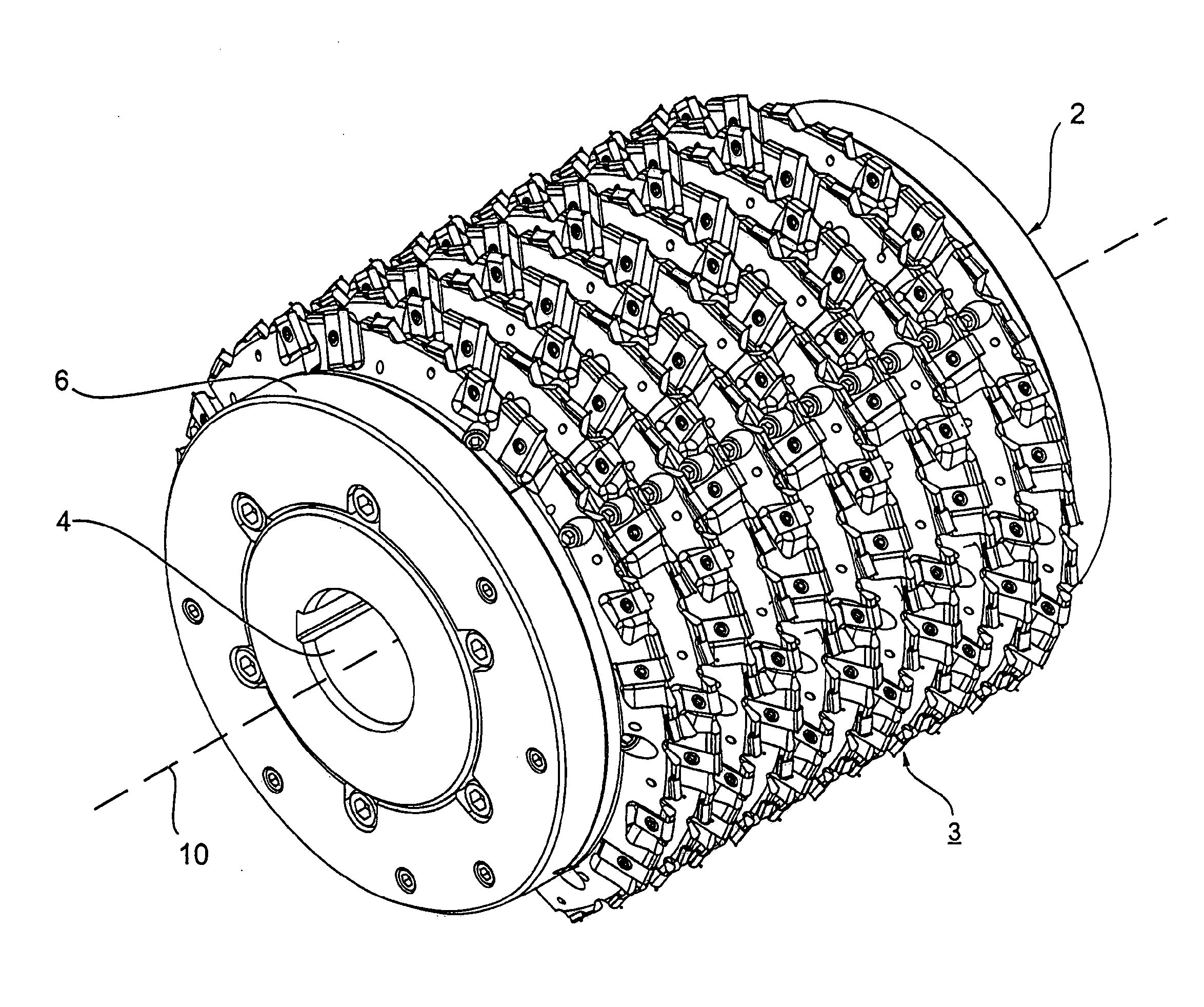
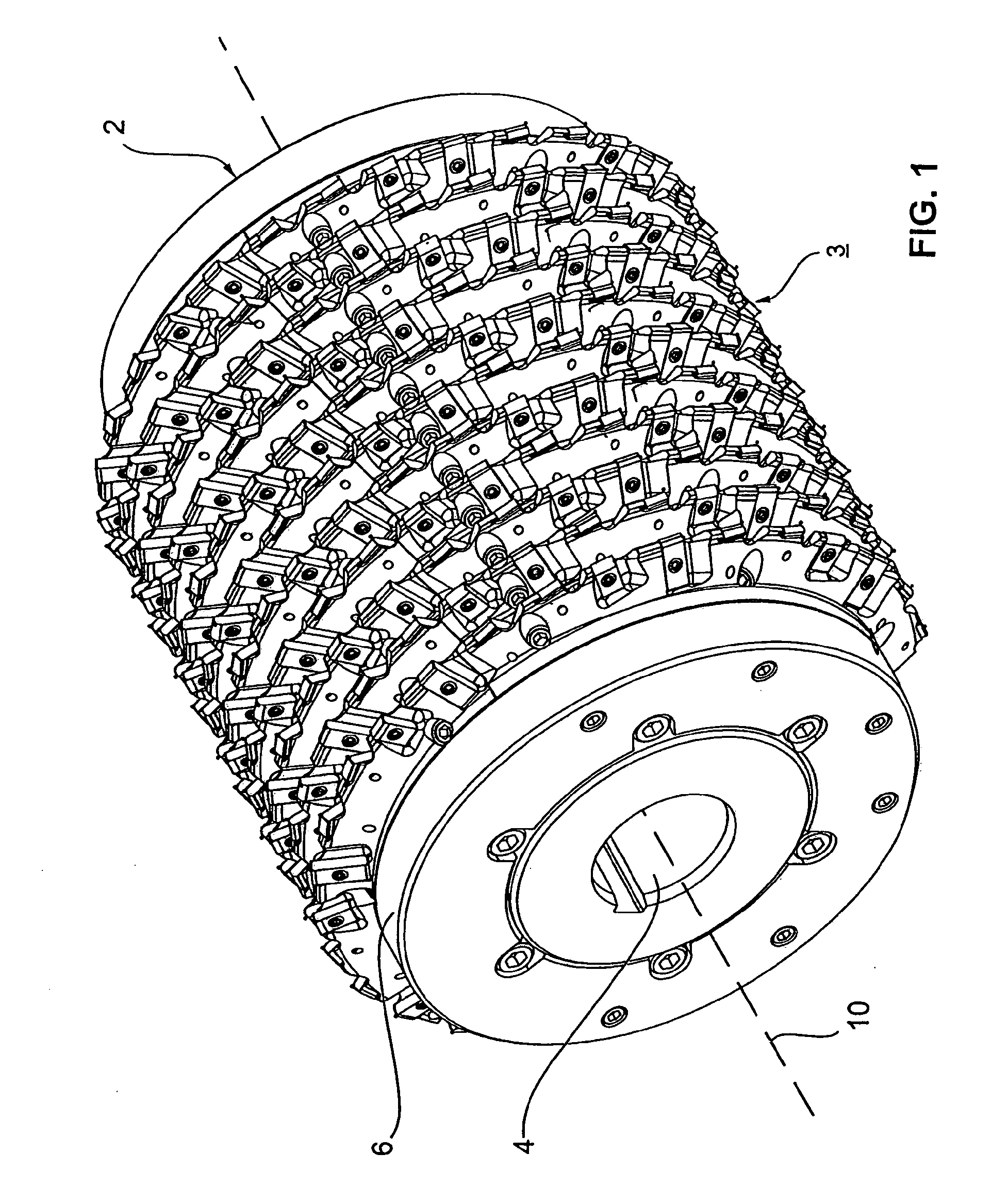
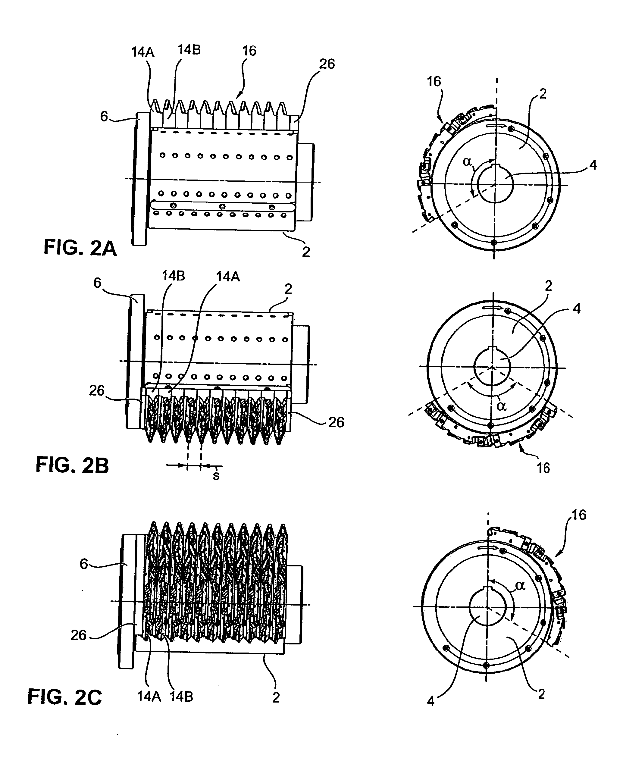
[0034]In the exemplary embodiment, the hob comprises a hollow cylindrical basic body 2 which is formed in the manner of a drum and to which a tooth profile 3 has been attached. The tooth profile 3 is wound helically on the lateral cylinder surface of the basic body 2 with a helix pitch s (cf. FIG. 2B). The basic body 2 (cf. in this regard in particular FIG. 5) has a central shaft receptacle 4, with which it can be secured to a driveshaft of a machine tool. At its rear end, the basic body 2 has an annular stop 6. A plurality of rows of screw holes 8 are provided in the lateral surface of the basic body 2. Introduced alongside these are grooves 12 that run in the longitudinal direction 10.

[0035]Fitted to this basic body 2 are a multiplicity of individual segments 14A,B, the detailed structure of which can be gathered in particular from FIGS. 3A to 3C and 4A to 4C.

[0036]As can be seen from FIGS. 2A to 2C, the individual segments 14A,B are secured to the lateral surface of the basic bod...


PUM


Abstract

A hob having a helically curved tooth profile. A plurality of segments covering only a limited angle range are attached to a base body for forming the tooth profile. The segments abut each other in the circumferential direction of the base body, and the segments form rows in the direction of the longitudinal axis of the base body. The segments each comprise a segment foot and a segment profile disposed diagonally thereon. The diagonal arrangement of the segment profile forms a coiled slope of the helically curved tooth profile in each segment and the tooth profile can be built up simply by arranging the segments in rows in the circumferential and the longitudinal directions.

Description

BACKGROUND OF THE INVENTION[0001]1. Field of the Invention[0002]The invention relates to a hob having a helical tooth profile.[0003]2. Description of Related Art[0004]A hob of this kind is disclosed in EP 0 050 270 A2. Hobs of this kind having helical tooth profiles are usually used for producing tooth profiles on gearwheels, for example on spur gears for transmissions. In order to form the helical tooth profile of the hob, cutting bodies are usually arranged in a distributed manner along a helix. These cutting bodies are often formed as cutting inserts, in particular indexable cutting inserts, which are secured in an exchangeable manner to a cross-sectionally roof-shaped carrier.[0005]DE-A 27 00 525 discloses a multipart hob, in which the tooth profile is formed by a plurality of encircling disks which are arranged in a row and each carry a disk-like gear rim. The individual disks are formed as annular disks which are arranged on a basic body in a row in the longitudinal direction....

Claims


Application Information

Patent Timeline
Patent Type & Authority Applications(United States)
IPC IPC(8): B23F21/16
CPCB23C5/2234B23C5/04Y10T407/1715B23F21/166Y10T407/1725
Inventor KRETSCHMER, ARMIN
Owner KENNAMETAL INC
Why Eureka
Try Eureka